
- Thu Mar 30, 2023 7:36 am
#62163
Hi D-Stage!!
Thank you so much for your amazing ETC. I'm currently using it to restore a 2005 Mastercraft. I have the controller functioning well in regards to opening and closing the throttle body. Unfortunately I can't get the D-Stage IAC to respond to Speedy.
I'm new to electronics so please bear with me with my experiments and descriptions of the problem
This is the throttle body I'm using. As you can see idle is controller by the butterfly rather than a valve.
https://www.amazon.com/gp/product/B071S ... UTF8&psc=1
So far I've connected an Uno to the IAC pad and simulated a PWM signal of 50% at 490 Hz, this results in the butterfly opening a few degrees. (this seems good)
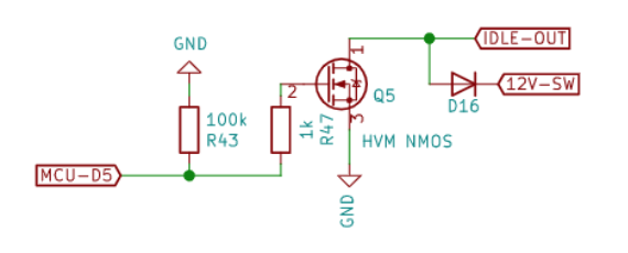
I've checked the Speedy circuit when powered up using the following diagram.
 Screen Shot 2023-03-29 at 5.24.01 PM.png (34.68 KiB) Viewed 3136 times
image.png
Screen Shot 2023-03-29 at 5.24.01 PM.png (34.68 KiB) Viewed 3136 times
image.png
I get the following voltages:
MCU-D5 = 2.5v
R43 = 2.5v
R47 = 2.5v
HVM NMOS leg number 2 = 2.5v
IDLE OUT shows no voltage.
On my Mastercraft thread PSIG has suggested the following:
viewtopic.php?f=18&t=5532&p=62146#p62146
"As Idle-Out is simply a grounding circuit, that also indicates that the device (ETC in this case) should have a 5V pullup, either internally or added into the circuit. This would function as 5V signal, grounded in pulses by Speeduino to create a 0V-5V signal to the ETC.
If all of that is making sense, when the ETC is powered-up, it should show 5V on its idle input, waiting to be grounded. If it does not, and all of this is confirmed by D-Stage, then it's either not enabled, or you need to add the 5V pullup. Again, I would verify with D-Stage."
I've checked the IAC pad on the ETC and it reads 0v.
At this point I'm a little beyond the limits of my understanding. Do you have any suggestions for next possible steps from here....?
Thanks once again for everything, without this controller I don't think I could have undertaken this project. After a year of completely rebuilding the boat this is hopefully the last issue I need to solve
Thank you so much for your amazing ETC. I'm currently using it to restore a 2005 Mastercraft. I have the controller functioning well in regards to opening and closing the throttle body. Unfortunately I can't get the D-Stage IAC to respond to Speedy.
I'm new to electronics so please bear with me with my experiments and descriptions of the problem
This is the throttle body I'm using. As you can see idle is controller by the butterfly rather than a valve.
https://www.amazon.com/gp/product/B071S ... UTF8&psc=1
So far I've connected an Uno to the IAC pad and simulated a PWM signal of 50% at 490 Hz, this results in the butterfly opening a few degrees. (this seems good)
I've checked the Speedy circuit when powered up using the following diagram.
I get the following voltages:
MCU-D5 = 2.5v
R43 = 2.5v
R47 = 2.5v
HVM NMOS leg number 2 = 2.5v
IDLE OUT shows no voltage.
On my Mastercraft thread PSIG has suggested the following:
viewtopic.php?f=18&t=5532&p=62146#p62146
"As Idle-Out is simply a grounding circuit, that also indicates that the device (ETC in this case) should have a 5V pullup, either internally or added into the circuit. This would function as 5V signal, grounded in pulses by Speeduino to create a 0V-5V signal to the ETC.
If all of that is making sense, when the ETC is powered-up, it should show 5V on its idle input, waiting to be grounded. If it does not, and all of this is confirmed by D-Stage, then it's either not enabled, or you need to add the 5V pullup. Again, I would verify with D-Stage."
I've checked the IAC pad on the ETC and it reads 0v.
At this point I'm a little beyond the limits of my understanding. Do you have any suggestions for next possible steps from here....?
Thanks once again for everything, without this controller I don't think I could have undertaken this project. After a year of completely rebuilding the boat this is hopefully the last issue I need to solve

 - By PSIG