Help with building your Speeduino, installing it, getting it to run etc.
By MGR550
#66088
Hello again, over a year later and little progress :oops:
On the bright side, there now exists: a bike in the living room for convenient access, a colour matched wiring diagram, 3d printed 36-1 trigger wheel, brackets, an intake manifold, exhaust w/ WBO2 bung, a rough map of ignition timing and other settings, and last but not least a complete speeduino-side wiring harness that needs to be lightly spliced into the main bike harness.

Please let me know if I've made any obvious errors in the wiring. I'd tested the TPS, CLT, IAT, sensors in the harness through tuner studio and all seemed to be responding well. Optical sensor I had working on the bench, but only recently got the trigger wheel done so that will go on the bike shortly. All the individual wire groupings are twisted to hopefully prevent noise if present.
I have a 10uF ceramic cap intentionally taped to my wiring harness but I can't remember where it was meant to go... IGN signal? optical sensor signal? Also unsure of how best to handle on/off re key power vs handlebar kill switch

Plan is to get wiring done soon and start getting all the I/Os working together at once. Goal is to get it ready to tune by spring.
Attachments
EFI RE-5 Speeduino Wiring Diagram.png
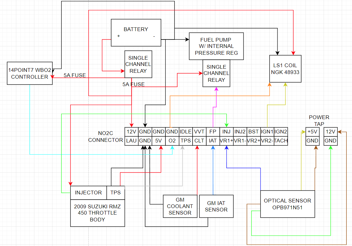
EFI RE-5 Speeduino Wiring Diagram.png (73.99 KiB) Viewed 1229 times
User avatar
By digmorepaka
#66094
MGR550 wrote: Fri Dec 01, 2023 4:11 am Hello again, over a year later and little progress :oops:
On the bright side, there now exists: a bike in the living room for convenient access, a colour matched wiring diagram, 3d printed 36-1 trigger wheel, brackets, an intake manifold, exhaust w/ WBO2 bung, a rough map of ignition timing and other settings, and last but not least a complete speeduino-side wiring harness that needs to be lightly spliced into the main bike harness.

Please let me know if I've made any obvious errors in the wiring. I'd tested the TPS, CLT, IAT, sensors in the harness through tuner studio and all seemed to be responding well. Optical sensor I had working on the bench, but only recently got the trigger wheel done so that will go on the bike shortly. All the individual wire groupings are twisted to hopefully prevent noise if present.
I have a 10uF ceramic cap intentionally taped to my wiring harness but I can't remember where it was meant to go... IGN signal? optical sensor signal? Also unsure of how best to handle on/off re key power vs handlebar kill switch

Plan is to get wiring done soon and start getting all the I/Os working together at once. Goal is to get it ready to tune by spring.
Looking good, couple notes:

-you should ground your coil's power ground against the rotor housing if possible along with just the battery connection. I see a couple conflicting pinout diagramns for the LS1 coil online, if this is the version with just the power ground on 2 pins, I would entirely omit the connection to speedy. Only connect it to speedy's ground if it has a dedicated signal ground.

-a 3d printed part is nice for test fitting, but other than a couple exotic methods it wont hold up to the heat(warpage is pretty bad for a trigger wheel), you should switch to a laser/plasma/waterjet cut metal trigger wheel once you are satisfied with your design

-killswitch, how dependent are the RE-5s on oiling? If they aren't super anal about it I would cut main power to speedy with the handlebar switch. This will instantly kill ignition and the fuel pump. I mainly work on 2 strokes, there with modern oils it's generally not an issue in the slightest to kill fuel supply while running and have it stall itself.


PS. would love to see pictures of the setup and the bike, always happy to see another motorcycle, especially one more exotic than a run of the mil 4 stroke 1cyl or literbike on here!
By stum
#66097
Only thing that jumps out at me is the fuse size to the Fuel Pump and Coil. 5A for both?? I have not played with a motorbike EFI pump before so not sure.

And a Good common -Ve, 0V, Ground point form Battery to Coil, Fuel Pump, Speeduino etc. I have been burned a few times with that.
By LPG2CV
#66098
Perhaps move the WB controller across to share the FP relay. That way, if the engine is stopped, but ignition on, then the WB heaters will turn off.
By MGR550
#66104
Thanks all for the good points.
Coil: I'm assuming that if all the other grounds are good enough it might not matter routing the signal ground the same as the power ground hence the 2 pinouts. I'll play it safe for now and keep what I think is signal ground at the speedy and the power ground I'll route to the rotor housing.
Trigger wheel: good point, I'll probably get once cut from a better material. Tip for others in North America: SendCutSend is fantastic for laser cutting metals and composites and such; lots of materials, fast turnaround and cheap.
Oiling/Killswitch: All the main bearings and gears have oiling just like a 4-stroke, only the apex seals rely on fuel/injected oil for lube. I'll be running a light premix as well as the stock gear driven little pump that draws from another reservoir and injects oil into the intake. Should be fine to kill via handlebar switch as long as thats still active + residual premix from fuel.
Fusing and WB: good points, I'll add the WB to the FP relay and re-think fusing requirements. Maybe a latching relay for the WB triggered by one of the unused IOs after its warmed up a bit or something. The WB sensor is maybe 10" or so from exhaust port so it will get hot pretty quick I think.
Fuel pump: I'm not confident in overall, its just a cheap ebay thing from china. Only draws 1.5A at load, but appears to work otherwise. Built in reg on an external pump is convenient for the retrofit.

Also some photos :D
Intake and exhaust ports on the rotor housing are both towards the front of the bike, between the rotor housing and the radiator, with the intake port more towards the top. Makes for very tight spacing on the intake and probably not great for intake airflow and heat management. Throttle cable splits into 5 different strands to actuate various things on the engine. Single spark plug on the rear side of the housing in the big open area under the seat and infront of the battery box.
Attachments
IMG_20210911_164956_082.jpg
IMG_20210911_164956_082.jpg (333.55 KiB) Viewed 1106 times
20231202_182050.jpg
20231202_182050.jpg (2.31 MiB) Viewed 1106 times
20231202_182015.jpg
20231202_182015.jpg (2.6 MiB) Viewed 1106 times
20231201_153330.jpg
20231201_153330.jpg (2.45 MiB) Viewed 1106 times
By LAV1000
#66111
Nice looking bike !
Fuelpump, make sure you have a type wich can deliver 3.0 bar/43 psi, most fuel injection stuff is rated to this type of pressure.
WB sensor heater, most WB controllers regulate heater, no need for special tricks, just cotrol it with the main relay.
As for latching relays, just keep it to normal automotive relays, its more a matter of keeping things simple, KISS principle.
By MGR550
#67237
Hello,
Re-did the wiring a bit in terms of fusing and relays, with an updated diagram to match. Got it wired into the bike, turning on and off with key and kill switch, reading sensors, and tested inj output so far. A bit of debugging and I got what I think is a clean signal from the trigger wheel . I'm guessing the plot is showing µs per rising edge to rising edge of next tooth? If the cyclic timing is from compression slowing it down, then my trigger wheel and crank aren't 1:1? rotary is 1 compression cycle/ crank rev right?
Seems my fuel pump isnt priming or turning on at all, is the pin assignment for the NO2C different than default in Tunerstudio? Should I expect the pump to turn on when the board is turned on or only when cranking?

Thanks
Attachments
(2.58 KiB) Downloaded 17 times
(79.47 KiB) Downloaded 18 times
EFI RE-5 Speeduino Wiring Diagram 2.0.png
EFI RE-5 Speeduino Wiring Diagram 2.0.png (69.55 KiB) Viewed 386 times
By LAV1000
#67246
About fuelpump,
When power aplied to speeduino it runs to prime the system and then stops.
It runs again when engine is starting/running.

Toothlogger looks good.
Vertical colom, hight eqauls time, so there is some kind of compression or mechanical cause which causes de difference in vertical collums.
I wouldn't worry about the difference in time between the non missing tooths
Have no idea how it should relate to the powerstroke on a rotary engine.
BMW E23 M30B28

Okay, I managed to start the engine. The &quot[…]

NO2C crank signal issues

Once again PSIG, thank you. Note this is set up fo[…]

I've managed to dig up a few obscure wiring diag[…]

Niiiice... 8-) Looking forward to your updates![…]

Still can't find what you're looking for?