Help with building your Speeduino, installing it, getting it to run etc.
User avatar
By TeamTortoise
#53821
Greetings all and thanks for such an active community I have been able to learn loads of stuff by lurking for a bit. I am just getting into my little project and have a NO2C board in the mail. My goal is to swap an older motor out of a jeep for a newer Manifold Injected motor and have a reliable runner that is fun to drive and tinker on. I had originally hoped to transplant the 1997-OBD2 computer but the more I learned the more headache and heartache were on the horizon.. Enter speeduino to save me.

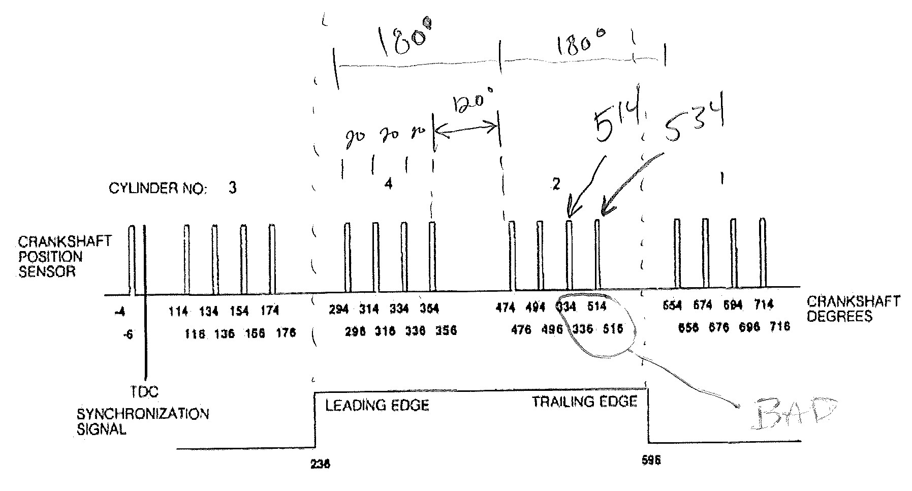
My first ask is for a double-check on some of my figuring and written code. I have researched out the Crankshaft sensor pattern for my flywheel and modified the jeep_2000 code. The cam is 180 degrees of "on". The crank has 4 notches 20 degrees apart and then a 120 degree wait for the next set. Tell me what you think? Anything I need to tweak. It will be a while before I get to test it as I still haven't got the new motor installed yet probably a week or two.
Jeep4cyl.jpg
Jeep4cyl.jpg (198.8 KiB) Viewed 4014 times
Code: Select all
/** @} */

/** Jeep 2.5L - 16 crank teeth over 720 degrees, in groups of 4 (1994 to 2002 2.5l 4 cylinder MPI Jeep engines).
* This is NOT for any of the PRE 1991 Renix Computer 2.5l motors with TBI. 
* Crank wheel is high for 360 crank degrees. Quite similar to the 24X setup.
* As we only need timing within 360 degrees, only 8 tooth angles are defined.
* Tooth number 1 represents the first tooth seen after the cam signal goes high.
* Signal should be high for 2 degrees. TDC should be at -6. 
* I Need to upload a new image to the forum for the 4cyl model. LINK HERE
* @teamtortoise JeepI4 (4cyl)
* Modified from: @defgroup dec_jeep Jeep 2000 (6 cyl)
* @{
*/
void triggerSetup_JeepI4()
{
  triggerToothAngle = 0; //The number of degrees that passes from tooth to tooth (primary)
  toothAngles[0] = 294;
  toothAngles[1] = 314;
  toothAngles[2] = 334;
  toothAngles[3] = 354;
  toothAngles[4] = 474;
  toothAngles[5] = 494;
  toothAngles[6] = 514;  //This is published wrong as 334 in some jeep manuals. 
  toothAngles[7] = 534;  //this is published wrong as 514 in some manuals. 
  

  MAX_STALL_TIME = (3333UL * 120); //Minimum 50rpm. (3333uS is the time per degree at 50rpm). Largest gap between teeth is 120 degrees.
  if(initialisationComplete == false) { toothCurrentCount = 9; toothLastToothTime = micros(); } //Set a startup value here to avoid filter errors when starting. This MUST have the initi check to prevent the fuel pump just staying on all the time
  secondDerivEnabled = false;
  decoderIsSequential = false;
  triggerToothAngleIsCorrect = true;
}

void triggerPri_JeepI4()
{
  if(toothCurrentCount == 9) { currentStatus.hasSync = false; } //Indicates sync has not been achieved (Still waiting for 1 revolution of the crank to take place)
  else
  {
    curTime = micros();
    curGap = curTime - toothLastToothTime;
    if ( curGap >= triggerFilterTime )
    {
      if(toothCurrentCount == 0)
      {
         toothCurrentCount = 1; //Reset the counter
         toothOneMinusOneTime = toothOneTime;
         toothOneTime = curTime;
         currentStatus.hasSync = true;
         currentStatus.startRevolutions++; //Counter
         triggerToothAngle = 120; //There are groups of 4 pulses (Each 20 degrees apart), with each group being 120 degrees apart. Hence #1 is always 120
      }
      else
      {
        toothCurrentCount++; //Increment the tooth counter
        triggerToothAngle = toothAngles[(toothCurrentCount-1)] - toothAngles[(toothCurrentCount-2)]; //Calculate the last tooth gap in degrees
      }

      setFilter(curGap); //Recalc the new filter value

      validTrigger = true; //Flag this pulse as being a valid trigger (ie that it passed filters)

      toothLastMinusOneToothTime = toothLastToothTime;
      toothLastToothTime = curTime;
    } //Trigger filter
  } //Sync check
}
void triggerSec_JeepI4()
{
  toothCurrentCount = 0; //All we need to do is reset the tooth count back to zero, indicating that we're at the beginning of a new revolution
  return;
}

uint16_t getRPM_JeepI4()    //Does this need to change? I am unsure what uint16_t refrences but it sure looks like 16 teeth from the previous map. 
{
   return stdGetRPM(360);
}
int getCrankAngle_JeepI4()
{
    //This is the current angle ATDC the engine is at. This is the last known position based on what tooth was last 'seen'. It is only accurate to the resolution of the trigger wheel (Eg 36-1 is 10 degrees)
    unsigned long tempToothLastToothTime;
    int tempToothCurrentCount;
    //Grab some variables that are used in the trigger code and assign them to temp variables.
    noInterrupts();
    tempToothCurrentCount = toothCurrentCount;
    tempToothLastToothTime = toothLastToothTime;
    lastCrankAngleCalc = micros(); //micros() is no longer interrupt safe
    interrupts();

    int crankAngle;
    if (toothCurrentCount == 0) { crankAngle = 236 + configPage4.triggerAngle; } //This is the special case to handle when the 'last tooth' seen was the cam tooth. 236 is the angle at which the crank tooth goes high.
    else { crankAngle = toothAngles[(tempToothCurrentCount - 1)] + configPage4.triggerAngle;} //Perform a lookup of the fixed toothAngles array to find what the angle of the last tooth passed was.

    //Estimate the number of degrees travelled since the last tooth}
    elapsedTime = (lastCrankAngleCalc - tempToothLastToothTime);
    crankAngle += timeToAngle(elapsedTime, CRANKMATH_METHOD_INTERVAL_REV);

    if (crankAngle >= 720) { crankAngle -= 720; }
    if (crankAngle > CRANK_ANGLE_MAX) { crankAngle -= CRANK_ANGLE_MAX; }
    if (crankAngle < 0) { crankAngle += 360; }

    return crankAngle;
}

void triggerSetEndTeeth_JeepI4()
{

  lastToothCalcAdvance = currentStatus.advance;
}
/** @} */
User avatar
By TeamTortoise
#53825
And now I'm a little sheepish because I totally missed another thread that makes it look like I copied my homework. At least it seems that my numbers check out with that project. I'm just excited, I'll try and calm down a little.
User avatar
By PabloSanhueza
#54088
Hello teamtortoise,
greetings from Chile and thank you very much for your code. I've been reviewing it and it makes perfect sense to me.
I have a 1996 2.5L I4 engine from Jeep XJ and its ECU burned out, so I decided to use a speeduino.
Did you get it to work?
These days I will try to start the engine and measure the signals with an oscilloscope in parallel with TS, but I am missing the MAP, injector and coil settings.
I hope your project turns out and that we can help each other, good luck!

regards!
By reliant_turbo
#56154
TeamTortoise wrote: Wed Nov 03, 2021 6:34 am And now I'm a little sheepish because I totally missed another thread that makes it look like I copied my homework. At least it seems that my numbers check out with that project. I'm just excited, I'll try and calm down a little.
No worries.... the more the merrier.

mine is currently reading RPM and syncing so far just fine though all i have hooked to the speeduino is the cam and crank sensors and power so its still running off of the stock ecu... which makes it easy to test inputs without worrying about tuning.

Brian
User avatar
By RowdyDouglas
#56551
Yeah, it's good to see others on here figuring it out. I realized today that my Trigger Angle ATDC should be -6 in my tune but I had it set to 0, oops. I think the Trigger Edge Rising|Falling is irrelevant since we have Hall sensors right?
Rowdy
User avatar
By digmorepaka
#56553
Some HAL sensors are active low some are active high so there is a difference. Shouldn't really matter as long as your setup is behaving reliably and the timing is accurate which you should always dial in with a timing light.
User avatar
By RowdyDouglas
#56604
My setup is not running yet so this may be part of my issue. I have my fuel pump disconnected while I troubleshoot. I need to set my Trigger Angle ATDC to -6, crank it for a few cycles then post log and tune to thread MODIFICATIONS TO JEEP 2000 DECODERS.INO FOR 2.5L OPERATION.

Respectfully
Rowdy
User avatar
By PSIG
#56610
The goal: Decoders are looking for specific physical "tooth" faces, hole edges, slot or gap ends, etc, either leading side or trailing side of that physical feature, as seen with the crank or cam turning in the normal direction. This physical feature is translated by a sensor to a signal, either rising or falling voltage. Additional signal processing may occur, that may invert the signal to the processor. It is our job to make tune settings from these variables so the processor "sees" the location of the intended physical edge.

Sensor polarity, possible signal conditioner inversion, and proper edge are all important with VR sensors. For digital sensors such as Hall, the number of issues are reduced, but still there. This makes it important to either follow a protocol (such as building the decoder on trailing edges), or making it obvious which edge is intended ("READS LEADING TOOTH EDGES").

Because we can't know the issues of sensors and signals for every setup, most decoders are built for timing with trailing edges on both crank and cam signals. Due to the possibility of a VR with inverting conditioner, the default tune setting is Rising edge (to detect trailing tooth edges ;)), and cam signals set for Falling as they are typically Hall sensors (again, a trailing tooth edge). This is to avoid the worst cases, but the default is random and edges should always be selected to only the proper Rising or Falling signal setting to read leading or trailing edge the decoder was built for or functions properly with.

As it is a specific decoder, the timing of the signals will shift with Trigger Edge selection. For crank patterns, it could be a little or a lot — 6° or 26°, etc, or become non-readable. It becomes critical when combined with a cycle ("cam") signal, such as this decoder, where incorrect edge will shift the pattern 360° in a 720° pattern. This may sync in some cases, but begin the sequence on the wrong cylinder (half-way through the firing order).

TL;DR — Determine the physical tooth edges the decoder needs to "see" for proper sync and timing, then configure the tune settings for your specific sensors and conditions so the ECM reads those intended tooth edges. 8-)
User avatar
By RowdyDouglas
#57536
Trigger Angle (Deg) "This number represents the angle ATDC (After Top Dead Center) when the tooth #1 passes the primary sensor".
Speeduino Download Manual says "Finding tooth #1 and trigger angle Please refer to the Trigger Patterns and Decoders for the trigger that you are using" but Jeep 2000 decoder page doesn't mention it https://wiki.speeduino.com/en/decoders/Jeep_2000.
Under fairly similar decoder for Dual Wheel "Tooth #1 is defined to be the first tooth on the primary wheel AFTER the pulse on the secondary wheel." "Trigger Angle: This is the angle in crank degrees AFTER TDC (ATDC) of the first tooth on the primary input, following the single pulse on the secondary input"
The Jeep decoder already knows tooth 1 [index 0] is at 294 but the secondary sensor angles aren't defined anywhere but in this setting. The first primary sensor tooth is 114 degrees ATDC but the first tooth after the secondary sensor pulse is 294 degrees ATDC, so I think I've convinced myself Trigger Angle (Deg) should be 294 degrees. However in the decoders.ino I am questioning the how this configPage4.triggerAngle is added to various crankangle calculations rather than just relying on the known toothAngles. I removed the adding configPage4.triggerAngle for crankangle calcs from a modified decoder I am about to try.
User avatar
By RowdyDouglas
#67262
Update, it works, I drove it around the block. I put in PR #931 but need to do timing, tuning and more road testing before the PR could be refreshed and merged.

I've managed to dig up a few obscure wiring diag[…]

Niiiice... 8-) Looking forward to your updates![…]

I'd be surprised if its not a 32-bit processor on[…]

I search for the datasheet of the IC and the on[…]

Still can't find what you're looking for?