

- Fri May 26, 2023 9:18 pm
#63228
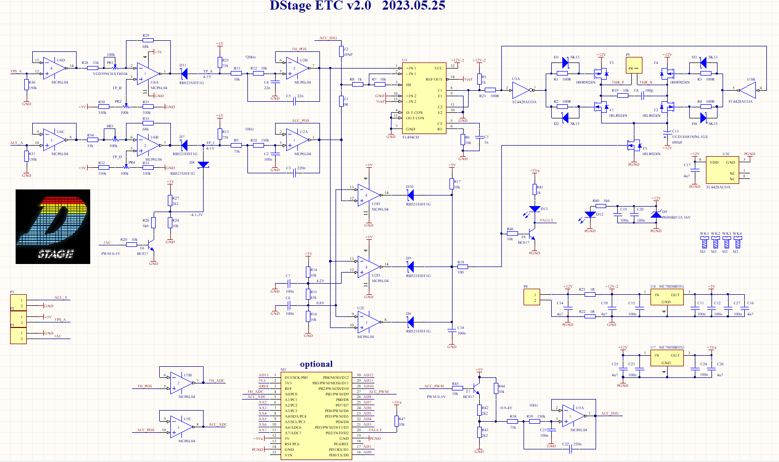 DStage ETC v2.0 Schematic.png (186.63 KiB) Viewed 7499 times
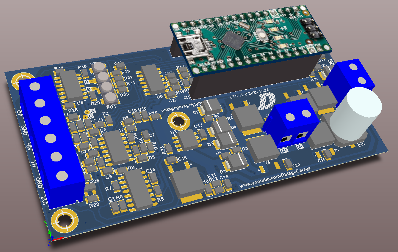 DStage ETC v2.0 PCB 3D.png (413.28 KiB) Viewed 7499 times
Hi everyone
After testing of v1.4 I realized that among other changes it requires adding two more op-amps. Since there was absolutely no space left in current form factor for new components I went for version 2.0 that changes the PCB dimensions significantly. I could extend it just a little and if anyone thinks this would still be a good option please let me know. However, the presented design is larger partially also due to optional add-on of Arduino Nano.
Here's the list of main improvements:
1. Calibration of gas pedal and TPS is now not based on resistance therefore vastly simplifies and improves usage of purely voltage positions signals (TPS and/or gas pedal based on hall and other non contact technologies).
2. More intuitive calibration and wider calibration range - input signal can be now multiplied by a factor from roughly 0.5 (division) to 2 (amplification/multiplication) and an positive or negative offset can be added. This should allow for very wide spectrum of signal dynamic range as long as it is within 0-5V boundaries.
3. signal conditioning (calibration) always giving same final boundaries of 1-4V which eliminates the need for modification of fail safe thresholds for non-pot based sensors.
4. LED indicator for main power and for fault condition meaning when fail safe kicks in. Optionally the fault LED can be connected externally using extra pads for soldering wires.
5. All standard inputs and outputs can now use screw terminals for easier connection. Terminals are not part of JLCPCB bom and have to be soldered manually but as those are big THT components this shouldn't be an issue. Optionally wires can be soldered directly in their place.
6. More fixing holes added. Board will fit few universal metal casings. I will also provide an STL file for 3D printing.
7. BOM already includes updated values for TPS filter that are proven to work fine |(no need for removing capacitors etc.) as well as changed R6 lowering motor PWM which results in much lower heat dissipation from power transistors.
8. Even though there are more components the final cost in JLCPCB is even a bit lower as all op-amps are now the same type which eliminates one of the extended part 3$ fee
The Arduino is here mainly for those who would like to have a build in map for the gas pedal so in other words non linear response from accelerator to the throttle opening. so far few people achieved that by using the boost map in Speeduino I think. The advantage of doing so is that it is available in TS but requires a bit of hacking. The option with build in Arduino gives a standalone option or no changes/hacks to Speeduino but map has to be added externally to TS. Again, if you think that's a bad idea please let me know. Please note that the main principle of operation even when using the map from Arduino stays analogue so for example the fail safes for broken or shorted wires on gas pedal and TPS lines stay the same which is a benefit over the hacks using boost map in Sppeeduino. Since Arduino is not in direct control over the feedback loop for throttle position but only translates gas pedal position the program does not have to be fast and optimal It's also worth mentioning that Arduino is completely buffered from the main analogue part via op-amps and transistors so most faults in the program won't cause fatal problems to the throttle.
Potentially there are other options such as communicating with Speeduino by serial or other interfaces but that of course means customization/extension of the code. Other usages for Arduino are also possible here, it can also asyst in tuning of the pots or control something else based on throttle position etc. It is totally optional though and ETC v2.0 can work without it just as the previous versions.
After testing of v1.4 I realized that among other changes it requires adding two more op-amps. Since there was absolutely no space left in current form factor for new components I went for version 2.0 that changes the PCB dimensions significantly. I could extend it just a little and if anyone thinks this would still be a good option please let me know. However, the presented design is larger partially also due to optional add-on of Arduino Nano.
Here's the list of main improvements:
1. Calibration of gas pedal and TPS is now not based on resistance therefore vastly simplifies and improves usage of purely voltage positions signals (TPS and/or gas pedal based on hall and other non contact technologies).
2. More intuitive calibration and wider calibration range - input signal can be now multiplied by a factor from roughly 0.5 (division) to 2 (amplification/multiplication) and an positive or negative offset can be added. This should allow for very wide spectrum of signal dynamic range as long as it is within 0-5V boundaries.
3. signal conditioning (calibration) always giving same final boundaries of 1-4V which eliminates the need for modification of fail safe thresholds for non-pot based sensors.
4. LED indicator for main power and for fault condition meaning when fail safe kicks in. Optionally the fault LED can be connected externally using extra pads for soldering wires.
5. All standard inputs and outputs can now use screw terminals for easier connection. Terminals are not part of JLCPCB bom and have to be soldered manually but as those are big THT components this shouldn't be an issue. Optionally wires can be soldered directly in their place.
6. More fixing holes added. Board will fit few universal metal casings. I will also provide an STL file for 3D printing.
7. BOM already includes updated values for TPS filter that are proven to work fine |(no need for removing capacitors etc.) as well as changed R6 lowering motor PWM which results in much lower heat dissipation from power transistors.
8. Even though there are more components the final cost in JLCPCB is even a bit lower as all op-amps are now the same type which eliminates one of the extended part 3$ fee
The Arduino is here mainly for those who would like to have a build in map for the gas pedal so in other words non linear response from accelerator to the throttle opening. so far few people achieved that by using the boost map in Speeduino I think. The advantage of doing so is that it is available in TS but requires a bit of hacking. The option with build in Arduino gives a standalone option or no changes/hacks to Speeduino but map has to be added externally to TS. Again, if you think that's a bad idea please let me know. Please note that the main principle of operation even when using the map from Arduino stays analogue so for example the fail safes for broken or shorted wires on gas pedal and TPS lines stay the same which is a benefit over the hacks using boost map in Sppeeduino. Since Arduino is not in direct control over the feedback loop for throttle position but only translates gas pedal position the program does not have to be fast and optimal
Potentially there are other options such as communicating with Speeduino by serial or other interfaces but that of course means customization/extension of the code. Other usages for Arduino are also possible here, it can also asyst in tuning of the pots or control something else based on throttle position etc. It is totally optional though and ETC v2.0 can work without it just as the previous versions.

 - By moussie369