For any add-on boards such as VR conditioners, optos and OEM interface boards
User avatar
By Broke4speed
#39794
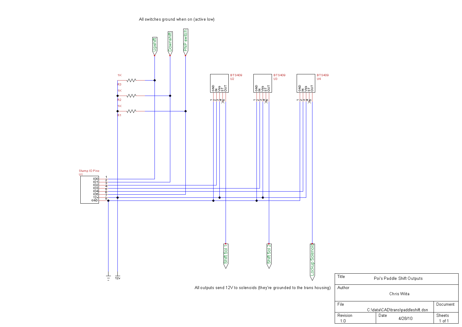
Sorry for being obtuse, I guess, but I'm confused why all the inputs (Park, Neutral, Drive, UpShift, DownShift) are INPUT/HIGH with pulldown resistors when it would be so much easier to make them all INPUT_PULLUP/LOW and run them right to ground. Is there a particular reason? Does the code require them to be high level inputs? It would be pretty easy to edit utils.ino, but how much would that affect?

I'm at work so I can't test anything, which is why I'm asking. All this is going by the schematic/diagram on the github for the non-sport version.
By dazq
#39805
In all honesty it was done as that was the shifter switching the initial testers had in place, it has always been considered that a input high or input low option was needed, as was an analog and even a canbus option( for which the later had some modified firmware testing done for a design being used on a Mercedes model )
User avatar
By Broke4speed
#39807
Code: Select all
      if (pinIn[1] < 255){pinMode(pinIn[1], INPUT);}
      if (pinIn[2] < 255){pinMode(pinIn[2], INPUT);}
So if I set it for INPUT_PULLUP, it should work? I've just tried compiling it after the change and it had no issues, but that (in my limited experience) doesn't always mean it would work, lol.
By dazq
#39808
Without reviewing the switching code i couldn't be certain , but iirc there would need changes made to the debounce as this was done in code.

Do you have a ground switching selector or is this just for testing?
User avatar
By Broke4speed
#39810
My selector is ground-switching. I'm not sure if I could run 5v through it, since it grounds through the bolts to the case. Isolating that could be tricky. I could always use the grounds to trigger relays or transistors and send a high signal to the mega though, if it came down to it.
User avatar
By Broke4speed
#40174
I'm throwing in the towel :(.
I just don't know enough about the code to implement a ground input for the RND/up/down inputs. Is there anyone who could offer some hints? My current A340E controller works just fine, but I'd like to run DxGears and try to contribute to the growth of the auto firmware testing. Being able to connect with TS would be a boon because right now all I have are three LEDs to let me know which solenoid is on/off.

The extra circuitry I'd need to use the current 5v pulldown setup would be kind of silly. I'd have to go from GND at the shifter switch to a relay/transistor that triggers a 5v feed to the inputs. Same thing goes for the up/down inputs. It would be so much simpler (and less complex) if I could just convert all the inputs over to INPUT_PULLUP.
By dazq
#40175
Broke4speed wrote: Fri Jan 03, 2020 3:18 pm I'm throwing in the towel :(.
I just don't know enough about the code to implement a ground input for the RND/up/down inputs. Is there anyone who could offer some hints? My current A340E controller works just fine, but I'd like to run DxGears and try to contribute to the growth of the auto firmware testing. Being able to connect with TS would be a boon because right now all I have are three LEDs to let me know which solenoid is on/off.
So to clarify , your selector /paddles , grounds the signal line when triggered and floats when not in use?

Also each action, p,r,n,d paddle up and paddle down each have a separate wire to the ECU?

It would be good to have the option to choose high or low side inputs , along with the analog and can ones.....
User avatar
By Broke4speed
#40177
dazq wrote: Fri Jan 03, 2020 3:24 pm

So to clarify , your selector /paddles , grounds the signal line when triggered and floats when not in use?

Also each action, p,r,n,d paddle up and paddle down each have a separate wire to the ECU?

It would be good to have the option to choose high or low side inputs , along with the analog and can ones.....
Yessir!

Currently, the basic controller I made out of a BASIC stamp from Parallax has a wire for up, a wire for down, and a wire for 'D' to let the code know when to function. Each of those wires are grounded when 'selected/used' and pulled up when not in use. This is the schematic I followed (the outputs are 5v logic just like the arduino):

Image

"PNP switch" is the 'drive' input. I could easily tap the remaining selector wires to get a reverse and neutral signal, and pull them up as well. It would be far simpler to use INPUT_PULLUP, since the selector switch on the A340E completes a ground to the case for it's 'signal' instead of 5v.
By dazq
#40213
I'm not near my test bench to try this out but I think you should be able to do get running with a simple mod.

In line 36 sensors.ino change the
if ( pinread == 1)
To
if ( pinread == 0)

I will look more at this when I am back on a bench , but please try this and let me know how you get on.
User avatar
By Broke4speed
#40216
Cool! I'll give it a whirl first thing tomorrow. I've got my test rig already set up.
Thank you very much, I'm pretty stoked :).
NO2C crank signal issues

Once again PSIG, thank you. Note this is set up fo[…]

I've managed to dig up a few obscure wiring diag[…]

Niiiice... 8-) Looking forward to your updates![…]

I'd be surprised if its not a 32-bit processor on[…]

Still can't find what you're looking for?