For discussion of Speeduino compatible boards designed / built by other members of the forum and for guidance around making such a board
By TheoKri
#39144
tooly wrote: Tue Nov 12, 2019 2:35 pm hope i will solder and test blitzbox2561cj125 next 2weeks.
Wow this is great!Keep us posted.Will need one of those for my pitbike.Awesome!
By TVRuk500
#40008
Hi Thomas,

How did you get on with your revised design?

I have been looking at the TLE8080 and was interested to understand how you are interfacing with the SPI to control your idle valve (IDV_OUT) and Fuel Pump (BP_OUT).

I can see that the outputs for fuel injectors are driven directly from the MEGA2561, on OUT1 & OUT3. The other outputs (OUT2, 4 & 5) are controlled via commands over SPI. Would you mind explaining how you are controlling this and the setup in firmware / Tunerstudio please?
User avatar
By chaoschris
#42868
Hi folks,
after fiddling a while with the atmega2561 design tooly and me decided to change the project to the standard atmega2560. We also changed the Molex connector to a TE variant with 34 pins. There is also a wideband lambda controller onboard (LSU 4.9) with the Bosch CJ125 and a separate Atmega328P to relieve the speeduino cpu. The whole design was optimized for automated assembly and is widely made in 0402 packages. hand soldering would be possible, but this is only for people with really experienced soldering skills or somebody with masochistic tendendencies.... ;-)
The design is mostly done, here are the actual specifications:
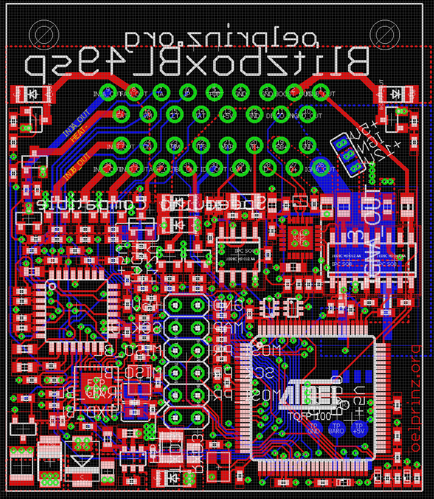
BlitzboxBL49sp
low-cost and mini-sized ECU for speeduino firmware (45 x 55 mm)
4 high impedance injectors
4 active ignition coils or 1 passive ignition coil with separate ground plane
1 crankshaft sensor with VR-conditioner
1 hall input for camshaft sensor
6 analog inputs: CLT, IAT, TPS, BAT, LMM, MAP
1 optional baro sensor MPXH6400A on bottom side
1 digital input for disco swaggering (aka. launch control)
Onboard Wideband Lambda Controller with Bosch CJ125 (LSU 4.9)
1 fuel pump out
1 idle valve out
1 tacho out
1 boost out
USB programming interface with CP2104

Link to the preview github: https://github.com/oelprinz-org/BlitzboxBL49sp

Any opinions or suggestions for improvement to this design are welcome. This project has the requirement to offer a really cheap ECU with all needed features to fire a 4 cylinder engine full sequential. And the first calculations are tending to be the the cheapest speeduino ecu on market altough there is a onboard wideband lambda controller on it. But first of all it must work how it was intended. We are trying to produce the first pieces to test it on the bench in some days.....

Best regards,
Chris
Attachments
2020-05-14 20_22_32-3 Board - C__Disks_Tools_Megasquirt_Derivate_Schaltplaene_BlitzboxBL49sp-master_.png
2020-05-14 20_22_32-3 Board - C__Disks_Tools_Megasquirt_Derivate_Schaltplaene_BlitzboxBL49sp-master_.png (270.44 KiB) Viewed 9605 times
top.png
top.png (206.38 KiB) Viewed 9607 times
bottom.png
bottom.png (130.02 KiB) Viewed 9607 times
(120.37 KiB) Downloaded 325 times
By madhunm
#42875
chaoschris wrote: Thu May 14, 2020 6:04 pm Hi folks,
after fiddling a while with the atmega2561 design....
Hi Chris,

Is this project going to be FOSS at all?

~M
User avatar
By chaoschris
#42879
Hello madhunm,
yes, all the needed design files to build this by yourself or getting it ready to use will be published in GitHub. Do you mean this with "FOSS"?
We also want to integrate this ecu into the speeduino firmware after testing it in a real environment.

The ecu with the 2561 is already on GitHub ( https://github.com/oelprinz-org/blitzbox2561cj125 ), but lacks further tests and you must integrate the TLE8080 on the software side. This design was intended to be cheap and soldered by hand.

The newer design with the 2650 isn't really intended for hand soldering (mostly in 0402 packages and really tight positioning of the parts) , but possible to do that. The design goal was to offer a ready-to-run ecu which is cheap and really small with all needed things onboard for a four cylinder full sequential.
Best regards,
Chris
By fram
#42881
Hi Chris

Nice design!
-USB data: will go through the harness without USB ground/shield?
-Missing USB+ into U11
-IC4 : Not sure about the schematic. You're using 2 ING signals to control IGBT, should we not have to ground the IGBT Emmiter ? could you explain?
;)
User avatar
By chaoschris
#42886
Hi Franck,

>>USB data: will go through the harness without USB ground/shield?

Yes. This is not optimal, but this should only be "harmful" in single coil operation. The ignition driver is on the bottom side and we have a ground layer as a shield inside (4-layer pcb). But we will see if this has any side effects in operation.


>>Missing USB+ into U11
Good eye..... Will be corrected soon. Not really urgent, but fixed now.


>>IC4 : Not sure about the schematic. You're using 2 ING signals to control IGBT, should we not have to ground the IGBT Emmiter ? could you explain?

If you want to drive coils with 4 active drivers, IC4 is not assembled, but R10 (0 Ohms) and R39 (47 Ohms). IGN_A will be provided via "COIL" to the outside. IGN_D will be the fourth ignition driver.
In the case of use a single coil without internal driver (single Cylinder oder with dristibutor) R10 and R39 are not assembled. IGN_A will drive the Gate of the Ignition driver IC4, COIL will be the low-end output of your Ignition coil and IGND_OUT will be your separate ground plane to motor ground. With this separate ground plane most of the dirty stuff should stay outside.

Best regards,
Chris
By madhunm
#42907
chaoschris wrote: Fri May 15, 2020 11:26 am Hello madhunm,
yes, all the needed design files to build this by yourself or getting it ready to use will be published in GitHub. Do you mean this with "FOSS"?
Chris,

Apologies, I used FOSS (Free and Open Source Software) instead of OSHW (Open Source HardWare).

Glad to know that the sources will be released.

~M
By Michael1
#43528
Hi , i like your project.Will you sell the boards?
I would be Interesting in a Board
Regards
Michael
User avatar
By chaoschris
#43552
Hi guys,
another step forward has been done in development of this ECU. The existing Revision 0.0.1 has got some slightly modifications.
There also exists a Revision 0.0.2 now which is 2 mm larger and has a NCV1124 VR-Conditioner onboard. This conditioner isn't our first choice, but available for SMT assembly. The MAX9924 is unfortunately not available for assembly and must be soldered by hand after production process.
What are your experiences with the NCV1124 VR-Conditioner? Are there any known no-go experiences? Please let us know...

All files like schematics, Gerber files, images and datasheets are as usual available on GitHub: https://github.com/oelprinz-org/BlitzboxBL49sp

Image

@Michael1: Of course there will be a chance to get a partly or full assembled board. But you have to be patient as there exists no prototype until now. It is planned to produce the first examples in one or two weeks.

Best regards,
Chris
  • 1
  • 2
  • 3
  • 4
  • 5
  • 21
Jeep transmission compatibility

Wanting to replace the old crappy Chrysler PCM in […]

blitzbox

Hi, It seems I can’t blame the error with t[…]

Thank you all for your input. I have managed to g[…]

Working on adding some different wheel definitions[…]

Still can't find what you're looking for?