
- Sat Jan 21, 2023 11:49 am
#60719
Hello, my name is John and i'm new to speeduino and arduino-microcontrollers in general although i'm quite experienced in electronics and mostly power supplies.
I have recently started building a Speeduino v0.4.3c PCB as per the official BOM and it is now complete.
I have a question since i'm testing the integrity of the board before i proceed with the Arduino so to not cause any damage.
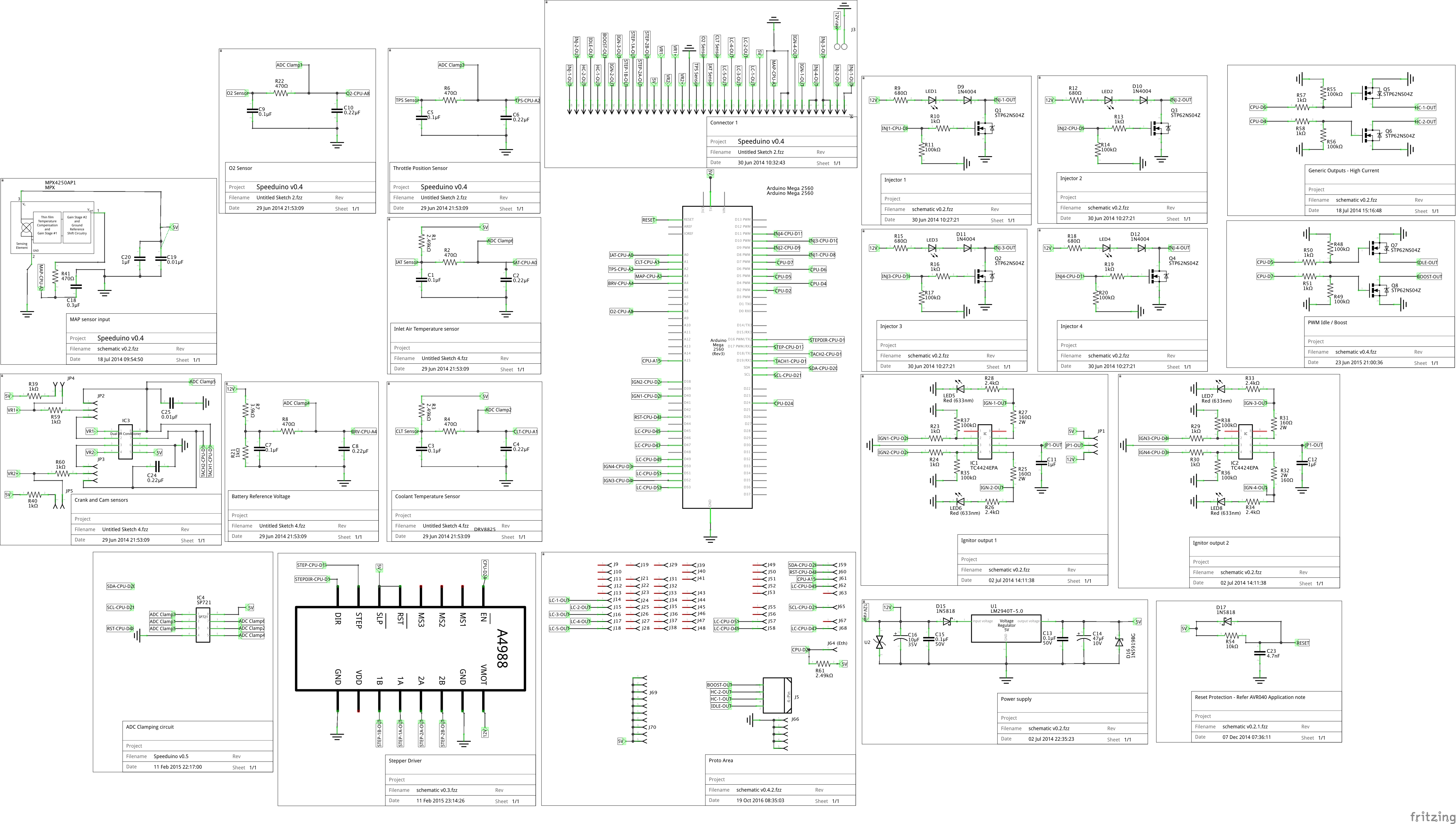
I connected the board to stable +12v using a battery, everything looks okay, nothing shorted, the board shows 10mA idle current consumption, nothing gets hot aswell.
I'm getting a perfect +5v from the regulator output which is also present on the 4424 ICs when IGN jumper set to 5v.
The problem is the +5v above the pins 20 and under Gnd on the left down corner only show +2.5v between +5v and ground.
I had installed a diode array consisted of 1N5819 schottky diodes instead of SP721APP, i thought this could be the problem but once i desoldered them i keep reading +2.5v on the pin 5 of the dip-8 on the board.
I traced the PCB and the 2.5v goes to R7 which has 2.5v on it's left and +12v on it's right, aswell as to the pin going to Pin 4 - Digital of the Arduino, making me think there's no immediate connection to +5v from the regulator there.
Is the so called "proto" zone powered solely by the arduino?
Isn't it supposed that the board will pass +5v from the regulator to those pins?
Or is the arduino somehow powering those pins which does not since it's not connected?
If those are powered by the Arduino, is it normal to find +2.5v there?
Sorry for the dumb question, i have absolutely ZERO knowledge to digital electronics.
I'm trying to be sure about the board before i proceed connecting the Arduino and possibly cause damage.
Thanks.
I have recently started building a Speeduino v0.4.3c PCB as per the official BOM and it is now complete.
I have a question since i'm testing the integrity of the board before i proceed with the Arduino so to not cause any damage.
I connected the board to stable +12v using a battery, everything looks okay, nothing shorted, the board shows 10mA idle current consumption, nothing gets hot aswell.
I'm getting a perfect +5v from the regulator output which is also present on the 4424 ICs when IGN jumper set to 5v.
The problem is the +5v above the pins 20 and under Gnd on the left down corner only show +2.5v between +5v and ground.
I had installed a diode array consisted of 1N5819 schottky diodes instead of SP721APP, i thought this could be the problem but once i desoldered them i keep reading +2.5v on the pin 5 of the dip-8 on the board.
I traced the PCB and the 2.5v goes to R7 which has 2.5v on it's left and +12v on it's right, aswell as to the pin going to Pin 4 - Digital of the Arduino, making me think there's no immediate connection to +5v from the regulator there.
Is the so called "proto" zone powered solely by the arduino?
Isn't it supposed that the board will pass +5v from the regulator to those pins?
Or is the arduino somehow powering those pins which does not since it's not connected?
If those are powered by the Arduino, is it normal to find +2.5v there?
Sorry for the dumb question, i have absolutely ZERO knowledge to digital electronics.
I'm trying to be sure about the board before i proceed connecting the Arduino and possibly cause damage.
Thanks.

