For discussion of Speeduino compatible boards designed / built by other members of the forum and for guidance around making such a board
User avatar
By turboedge
#17383
So, I got impatient waiting for parts to make it to my house from the far reaches of the planet and I started drawing a smaller version of the current official Speeduino boards. It is mostly a v0.4 with accessories removed, resistor networks/arrays, 2 injector and ignitor channels. I wanted to have it fit within the confines of the mega board and still use through hole parts to make it easier to assemble like the original Kartduino. The connectors are Molex KK254 (like computer fans). Since my first project is to be a small engine I thought a design like this would work well.

This is my first time using KiCAD or drawing a board. So what do you think? Will it work? Suggestions? Thanks!
Attachments
NO2C v0.1-FRONT.png
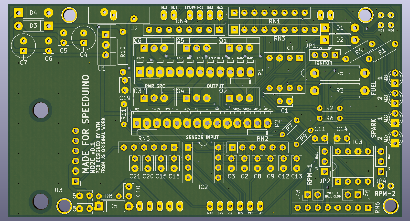
NO2C v0.1-FRONT.png (1.31 MiB) Viewed 12448 times
NO2C v0.1-BACK.png
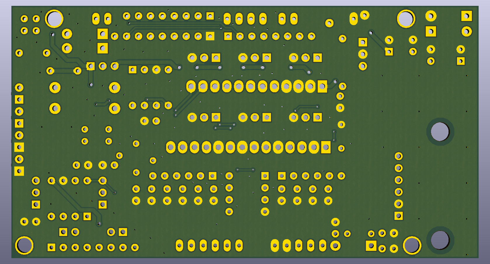
NO2C v0.1-BACK.png (1.04 MiB) Viewed 12448 times
By noisymime
#17384
As far as the electronics go, if it's based on the existing schematics and you have implemented them faithfully, there's absolutely no reason at all why it shouldn't work :D

Definitely let us know how it all comes together!
User avatar
By turboedge
#17506
Is the TC4424A a suitable replacement for the TC4424, or would it require adjustments to the design? The datasheet indicates that it is a pin compatible newer revision with what appears to be better specs. Digi-key indicates that the old version is not for new designs and the newer "A" version is cheaper.

Thanks!
User avatar
By turboedge
#17507
I have officially made Swiss cheese :D . I sent this to manufacturing. In my excitement I forgot I wanted to update the silkscreen to include TAPR :roll: . If anyone wants any part of this let me know, I will get it to you.
Attachments
NO2C-W-STEPPER-FRONT.png
NO2C-W-STEPPER-FRONT.png (1.26 MiB) Viewed 12392 times
NO2C-W-STEPPER-BACK.png
NO2C-W-STEPPER-BACK.png (1005.62 KiB) Viewed 12392 times
User avatar
By ElDominio
#17515
I love this.

I've considered also slimming down the code and making it run on a Pro Mini , which would make the package size considerably smaller and cheaper. I'm keeping tabs on your thread, and this really motivates me to start yanking code off Speeduino main code and make it not work correctly! lol
By noisymime
#17525
turboedge wrote: Tue Mar 28, 2017 4:49 pm Is the TC4424A a suitable replacement for the TC4424, or would it require adjustments to the design? The datasheet indicates that it is a pin compatible newer revision with what appears to be better specs. Digi-key indicates that the old version is not for new designs and the newer "A" version is cheaper.
Yep, no issues at all with using the A versions of these parts.
User avatar
By turboedge
#17548
Thanks for the kind words ElDominio! I think you have your work cut out for you shrinking it down to the pro mini's 32K, but if it can be done I think it would be great for small engine applications. I confess I have still not even fired up the mega to see what's what, and this will be my first Arduino project. I've been wanting to do a controller project for a while, could not decide what to do. Then I found this, computer controlled engines :lol: !

Thanks noisymime for verifying that for me. I thought that would be the case, but I could not find a for certain answer anywhere. Love the project. Thanks for all the effort you have put into it!

Now I must wait :( . Hopefully not too long. I keep thinking of more tweaks to make to it, but it's locked in now. Maybe release v0.1.1, if there ever is such a thing. Now I have to figure out what hardware to use for my application, gives me something to do while I wait I suppose.
User avatar
By turboedge
#18144
As promised, assembled pics of v0.1 where you can clearly see the issues. The stepper module is unusable due to interference with the USB connector. The other issue is with my use of the AMP crimp-less connector and the height of the MOSFETs. It will work for my single channel, no stepper required needs though.

I will continue to tweak it until I find the results acceptable and then I will post the files here.
Attachments
IMG_4468.JPG
IMG_4468.JPG (1.24 MiB) Viewed 12171 times
IMG_4467.JPG
IMG_4467.JPG (911.7 KiB) Viewed 12171 times
User avatar
By PSIG
#18147
Looks good though! Perhaps just move the stepper to the MAP location, and put an MPXH6250 over the USB. They are big enough to solder by hand. The TO-220 height may not be a problem, as the wires need radius space to turn 90° anyway?

David
  • 1
  • 2
  • 3
  • 4
  • 5
  • 17

nice first of all, i read all that crap months a[…]

I rewired a few grounds and tested the TPS and rel[…]

Thanks, car runs great now !!! Going to drift even[…]

sauver moteur v8

bonsoir je m appel jean marie et j habite en Franc[…]

Still can't find what you're looking for?