Help with building your Speeduino, installing it, getting it to run etc.
User avatar
By PSIG
#16358
Ummm... according to the ULN2803 data sheets, the COM should be tied to the load voltage supply, not board 5V, right? That would be bad.
TI.com wrote:When the COM pin is tied to the coil supply voltage, ULN2803A is able to drive inductive loads and supress the
kick-back voltage via the internal free wheeling diodes.
You can use a ULN2803 on a v0.4.2, but it has to be jumper-wired in the proto area. I ordered 10 extra ULNs for this purpose. I have asked for an 'official' aux driver outline for the Wiki so users can build their units for outputs on the aux pins, such as my need for more than the four HC aux outs, but no solutions yet.
David
ULN2803_Inductive_Load_COM.png
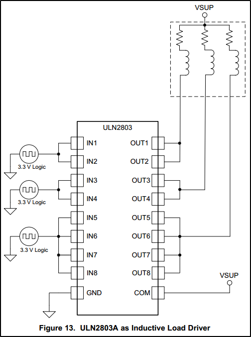
ULN2803_Inductive_Load_COM.png (44.46 KiB) Viewed 10981 times
By TDSA
#16373
dazq wrote:
TDSA wrote:
dazq wrote:Whatched the video, it was just a brief glimps as you moved on fast and the image is small, but im sure i saw you have both fuel and vvt outputs set to 4
Can you please post you utils.ino on here so we can look it over ? Thanks
I changed the PinVVT1_12 (same as injector 5 and PinLaunch) for now - uploaded the firmware to the arduino, and same issue exists.

Fuel pump will not switch on at all.
No two pins should ever share the same value. Just make vvt = 47. I dont see that on the screen shot but check.
Thanks alot - i have done the and still no voltage read from the FuelPump pin 35 on the IDC40 connector....??? Thermo Fan is working 100% though

Could there be another software related issue or is it the manner in which i am testing the feature?
I have checked the solder joints, and hardware side of things, and everything is 100% --

frustrating the hell out of me now - wanna build another board and test IT -- I'm starting to doubt all sorts of things...... :oops: :oops:
By TDSA
#16374
PSIG wrote:Ummm... according to the ULN2803 data sheets, the COM should be tied to the load voltage supply, not board 5V, right? That would be bad.
TI.com wrote:When the COM pin is tied to the coil supply voltage, ULN2803A is able to drive inductive loads and supress the
kick-back voltage via the internal free wheeling diodes.
You can use a ULN2803 on a v0.4.2, but it has to be jumper-wired in the proto area. I ordered 10 extra ULNs for this purpose. I have asked for an 'official' aux driver outline for the Wiki so users can build their units for outputs on the aux pins, such as my need for more than the four HC aux outs, but no solutions yet.
David
ULN2803_Inductive_Load_COM.png

David,

Please could you share more info with me on how you wired it up and what changes yo made inside the .ino files -- i also would like more HC outputs.
In fact i don't ming the LC outputs with Relays, but they don't seem to work at all, hence why i went the HC output route and changed the utils.ino file to suite - but still no fuel pump working..?
#16376
You are going to need to troubleshoot why the HC output isn't working. Likely a hardware issue at this point. What I would do:

Go back and make sure components are correct and nothing is in the wrong place, reversed, etc.
Ensure all solder joints are good, and there are no bridges (areas where solder covers two points that should be separate).

Change the priming pulse to 10 seconds to make this easier:
Probe the arduino pin (D4) to see if it is toggling from ground to +5 volt when started up. If not, separate the arduino from the speedy board. Plug in the usb to power it while checking pin D4. If no toggle, try another Arduino - if that one doesn't work, it is still a firmware problem

If it does toggle, check to see if it toggles on the gate of Q5 (pin 1 below). Check that pin 3 is connected to ground and that pin 2 has continuity with IDC pin 35. If these pass, change the MOSFET, it may be bad.
If no toggle at the gate of the MOSFET, check for again breaks in the traces, shorted components, etc.
Attachments
Capture.JPG
Capture.JPG (12.61 KiB) Viewed 10970 times
By TDSA
#16414
apollard wrote:You are going to need to troubleshoot why the HC output isn't working. Likely a hardware issue at this point. What I would do:

Go back and make sure components are correct and nothing is in the wrong place, reversed, etc.
Ensure all solder joints are good, and there are no bridges (areas where solder covers two points that should be separate).

Change the priming pulse to 10 seconds to make this easier:
Probe the arduino pin (D4) to see if it is toggling from ground to +5 volt when started up. If not, separate the arduino from the speedy board. Plug in the usb to power it while checking pin D4. If no toggle, try another Arduino - if that one doesn't work, it is still a firmware problem

If it does toggle, check to see if it toggles on the gate of Q5 (pin 1 below). Check that pin 3 is connected to ground and that pin 2 has continuity with IDC pin 35. If these pass, change the MOSFET, it may be bad.
If no toggle at the gate of the MOSFET, check for again breaks in the traces, shorted components, etc.
Apollard,

Thanks for the info - here are the results of the test ---

1) D4 on the arduino (while plugged into the Speeduino board) does switch on 5V when the power supply is turned on - for 10 seconds and switched off. So the Arduino and firmware is 100% -
2) Pin1 of Q5 does toggle 5V when the power supply is turned on - so this is a pass
3) Pin 2 of Q5 does NOT have continuity with IDC35 -- BUT is DOES have continuity with Pin36 next to it.....

Do i change the Mosfet??

Another thing i noticed while i was handling the speeduino - that U1 it very hot, burned my finger!!! ?? Is this normal?
#16422
TDSA wrote: Apollard,

Thanks for the info - here are the results of the test ---

1) D4 on the arduino (while plugged into the Speeduino board) does switch on 5V when the power supply is turned on - for 10 seconds and switched off. So the Arduino and firmware is 100% -
2) Pin1 of Q5 does toggle 5V when the power supply is turned on - so this is a pass
3) Pin 2 of Q5 does NOT have continuity with IDC35 -- BUT is DOES have continuity with Pin36 next to it.....

Do i change the Mosfet??

Another thing i noticed while i was handling the speeduino - that U1 it very hot, burned my finger!!! ?? Is this normal?
U1 does get hot and can sometimes get hot enough to go into protection mode and shutdown. I've used small stick on heat sinks for this. Recently, I've substituted switching units intended as a replacement.

Sorry, I typed wrong - Pin 2 of Q5 should connect to IDC pin 36, not 35 so that is OK.

Does Pin 3 of Q5 connect to ground? If it does, it should work.

One last item to try - hook a known good 12V bulb to IDC pin 36 and your 12V supply positive. The bulb should toggle upon startup.

Let us know if Pin 3 is grounded and if the bulb toggles.
By TDSA
#16443
apollard wrote:
TDSA wrote: Apollard,

Thanks for the info - here are the results of the test ---

1) D4 on the arduino (while plugged into the Speeduino board) does switch on 5V when the power supply is turned on - for 10 seconds and switched off. So the Arduino and firmware is 100% -
2) Pin1 of Q5 does toggle 5V when the power supply is turned on - so this is a pass
3) Pin 2 of Q5 does NOT have continuity with IDC35 -- BUT is DOES have continuity with Pin36 next to it.....

Do i change the Mosfet??

Another thing i noticed while i was handling the speeduino - that U1 it very hot, burned my finger!!! ?? Is this normal?
U1 does get hot and can sometimes get hot enough to go into protection mode and shutdown. I've used small stick on heat sinks for this. Recently, I've substituted switching units intended as a replacement.

Sorry, I typed wrong - Pin 2 of Q5 should connect to IDC pin 36, not 35 so that is OK.

Does Pin 3 of Q5 connect to ground? If it does, it should work.

One last item to try - hook a known good 12V bulb to IDC pin 36 and your 12V supply positive. The bulb should toggle upon startup.

Let us know if Pin 3 is grounded and if the bulb toggles.

OK - got this to work now..... seems that there is a pin mix up on the 0.4.2 boards that hasn't been mentioned, and doesn't marry up to the wiki schematics....

1) Pin7 is required to be selected in TS (Not Pin5) in order to have the Fuel pump working on IDC40 Pin35 -- tested and works 100% now.
2) Pin4 switches to Q5 and is connected to IDC40 Pin37 and controls the Thermo Fan - pin4 is required inside TS aswell

Next challenge is finding out which pins VVT, Stepper Idle, PWM Idle, and Boost control are connected to....... :shock:
User avatar
By PSIG
#16588
There is no 'official' solution for outputs yet. My best answer for the combination of HC and LC outputs, is that:
  • Idle, VVT, and Boost should be on HC outputs for direct-drive of the devices by PWM.
  • Other outputs (Fan, Fuel Pump and TachOut) can be either HC or LC, to external relay or direct (TachOut).
  • LC outputs from Mega D43 to D51 require a clamped driver of some kind, such as transistor with diode, ULN2803, or similar to drive a relay.
  • All outputs except Idle are assignable in TS.
As for what to do about the LC output drivers, either discreet transistors/FETs of some suitable kind, or the ULN2803 type can be installed in the 'proto' area. If using the ULN2803 as listed in the v.04 BOM, it can be installed with ULN leg 9 in PCB GND on the board and up across the D51 to D43 outputs for the ULN inputs. Cut ULN leg 8 if A15 might be used on Speeduino. I would just cut it.
:!: Lift ULN leg 10 and solder a wire from the leg to raw (Vbat) 12V+ on J3 or other raw 12V+ point such as U2, C16, C15, or JP1. Diagonally across the board would probably be best to minimize induction of noise. DO NOT allow ULN pin 10 to touch any part of the board except the wire connection to +12V! :!:
Either spread the ULN legs to reach the points to connect to the IDC 40-pin outputs on IDC pins 14 through 18, or bridge the connections on the board. Select the LC outputs active on D51 to D43 in TunerStudio as-required (or reassign LC and HC pinouts), and verify no conflicts with other outputs designated. Note: due to protection diodes in the ULN, the tachometer output is OK for 5V or 12V triggering with a pullup, but not flyback pulses ("relay coil" method) as the diode shorts the pulse voltage. Good luck!

David
ULN_on_v04x.jpg
ULN_on_v04x.jpg (138.3 KiB) Viewed 10873 times
Last edited by PSIG on Sat Nov 02, 2019 1:47 pm, edited 2 times in total.
  • 1
  • 3
  • 4
  • 5
  • 6
  • 7

Had it running for a short period again. Same as […]

Ok, here is the first version of the adapter plate[…]

Ignition Angle doubled?

don't load your old tune in case it is corrupted[…]

Yes, totally wrong setting. Slight noise in TPS ca[…]

Still can't find what you're looking for?