For any discussion not specifically related to your project
#51010
OK so I've been reading allot on this rising vs falling edge trigger because I've been having some random and very rare syncloss .
My setup is vr sensor on missing tooth 60-2 wheel and a missing tooth cam wheel.
I attached a screenshot of my trigger settings and a snapshop of a syncloss event.
My Jumper setting for trigger inputs are Jp2, Jp3 are on VR ( my cam hall sensor is 0-12v), JP4,JP5 are off
I also have an inline resistor for the vr sensor input because it was not revving past 2500 without it. (I think it was 10k resistor,need to check)
I have to mention that my syncloss is very very rare in 10 pulls to 6000rpm i may get 1 syncloss event.
As I understand it I have to remove C25 and C24 caps to avoid advance retard at high RPM is that correct?
Also will this help with the sync-loss or do I need to look somewhere else?
Attachments
syncloss.png
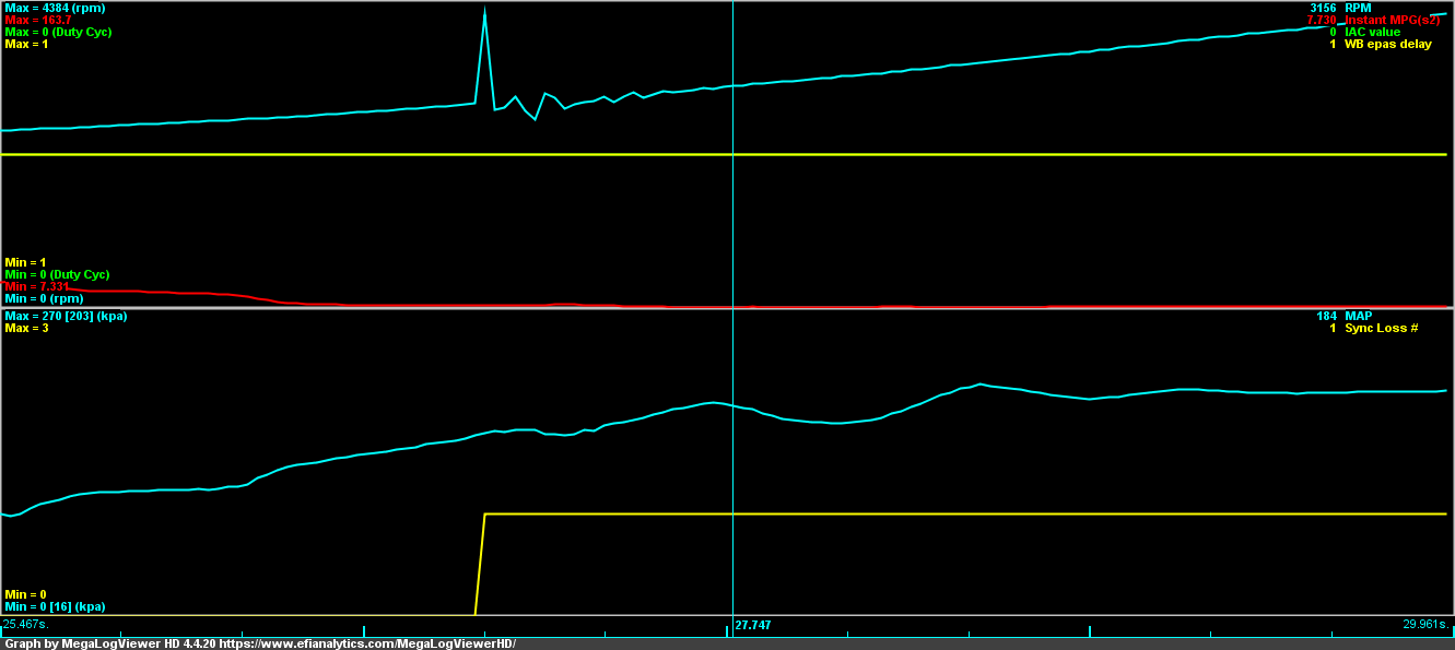
syncloss.png (26.09 KiB) Viewed 4950 times
trigger.jpg
trigger.jpg (91.08 KiB) Viewed 4950 times
#51018
moonie223 wrote: Fri Jun 11, 2021 4:38 pm What conditioner are you using that doesn't have serial resistors on all the inputs? One you designed?

What caps? There should be none on the output.

What board, what VR conditioner? What are these jumpers you reference?
The board is 0.4.3 I forgot to mention.

Conditioner is a standard speeduino dual VR that I purchased pre assembled. And yes of course it has inline resistors 1K ones...but it was not enough for the VR input so i changed for a higher value...
What do you mean there should be no caps on the output?? Check out the schematic for the 04 board and you will see c24 and c25 there
and the jumpers..what can I say..I think you are not familiar with the 0.4 boards..
#51019
The conditioner should have 10K series resistors on the inputs and no capacitors on the digital output, if it does than I can see it having problems. It could be you damaged the MAX9926 clamp diodes which are loaded in normal use. If your VR puts out more than 40V then according to the datasheet you smoked it.

I am familiar with some speedy hardware which IMO isn't that great. As an example, why would you need filter capacitors on what is supposed to be a filtered output? IMO, they should be DNP when using a max9926 board.

Why would you put 1K series resistors on the max9926? The reference diagrams from the datasheet work perfectly fine...
#51020
moonie223 wrote: Fri Jun 11, 2021 5:28 pm The conditioner should have 10K series resistors on the inputs and no capacitors on the digital output, if it does than I can see it having problems. It could be you damaged the MAX9926 clamp diodes which are loaded in normal use. If your VR puts out more than 40V then according to the datasheet you smoked it.

I am familiar with some speedy hardware which IMO isn't that great. As an example, why would you need filter capacitors on what is supposed to be a filtered output? IMO, they should be DNP when using a max9926 board.

Why would you put 1K series resistors on the max9926? The reference diagrams from the datasheet work perfectly fine...
It seems you should not comment about an ecu you do not know anything about...
#51021
I would first run a tooth log at 3k rpm for clues, or (better) look at both the upstream and downstream signals with a 'scope, so you can "see" what you're dealing with. It may be that you are simply too close to the edge with your resistor selection, or noise, or signal stability, etc. Then with the additional info I would look at options for solutions from there, or have a better idea of where to look for more clues. This is diagnostic troubleshooting.
#51023
jackscr wrote: Fri Jun 11, 2021 6:56 pm
moonie223 wrote: Fri Jun 11, 2021 5:28 pm The conditioner should have 10K series resistors on the inputs and no capacitors on the digital output, if it does than I can see it having problems. It could be you damaged the MAX9926 clamp diodes which are loaded in normal use. If your VR puts out more than 40V then according to the datasheet you smoked it.

I am familiar with some speedy hardware which IMO isn't that great. As an example, why would you need filter capacitors on what is supposed to be a filtered output? IMO, they should be DNP when using a max9926 board.

Why would you put 1K series resistors on the max9926? The reference diagrams from the datasheet work perfectly fine...
It seems you should not comment about an ecu you do not know anything about...
Rodger that. Best of luck to you.
#51027
PSIG wrote: Fri Jun 11, 2021 7:11 pm I would first run a tooth log at 3k rpm for clues, or (better) look at both the upstream and downstream signals with a 'scope, so you can "see" what you're dealing with. It may be that you are simply too close to the edge with your resistor selection, or noise, or signal stability, etc. Then with the additional info I would look at options for solutions from there, or have a better idea of where to look for more clues. This is diagnostic troubleshooting.
OK I ran a tooth log but the pattern is fine, nothing weird( but yeah it is such a sporadic occurrence that who knows when it will show up)... or are you saying run the log without the extra resistor inline?
Also I have to mention that this exact setup including the inline extra resistor ran fine with the previous megasquirt 2 ecu and the mega also would not run without the resistor inline and rpm would break up above 2-3k (so I found this solution with the resistor as being quite common in the MS world)
Thank you for help and I hope moonie did not take it the wrong way but he seemed to criticise the basic layout of the ecu that I could not change.
I embarked on the speeduino bandwagon just for the hell of it (this car is basically a test mule for all kinds of stuff I come up with ) I managed to overcome all sorts of issues so far and I got it running pretty good with seq injection,water injection, closed loop idle and boost , vss input(waiting for boost by gear:). I just need to work out the extra analog inputs that are acting up and this syncloss that appeared out of nowhere..

nice first of all, i read all that crap months a[…]

I rewired a few grounds and tested the TPS and rel[…]

Thanks, car runs great now !!! Going to drift even[…]

sauver moteur v8

bonsoir je m appel jean marie et j habite en Franc[…]

Still can't find what you're looking for?