For any discussion not specifically related to your project
#47063
I broke a Bosch LSU 4.9 and I think Speeduino can help avoid that. I learned I need to power up the wideband controller only after the engine is running, otherwise it will get damaged. Bummer. I found this explanation:
https://www.nzefi.com/bosch-lsu-wide-ba ... lications/
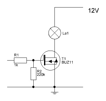
So, I would like a delayed signal from the Speeduino to drive a relais. I know people use the fuel pump wiring, but that also starts before the engine runs. Would it be possible to use Speeduino 0.4 port 14 (proto area, I don't use a flex fuel sensor) to generate this signal, using the 'Programmable outputs' in TS? Never mind the chosen output pin number, but something like this pic

Image

Using an unused port of the ULN2803 already there for the fuel pump relais and the fan relais?
Cheers,
Hugo
#47170
Hi,

I have searched a little more by lack of answers here, I hope someone can chime in. I was told the high current outputs can easily power my wideband controller. And since I have a two-wire AIC valve, I have Speeduino 0.4.4 pin 36, Mega pin 6, free to use for my application. But I cannot get it to work. Here are my settings for thise rule:
WBC settings.PNG
WBC settings.PNG (19.82 KiB) Viewed 5134 times
The idea is my wide band controller is switched on 10 seconds after the engine starts. It will be made 20 seconds once I got the system working. But it doesn't do anything. I measure at Speeduino pin 36 and ground, in my view I should get 14V 10 seconds after the engine started. But it doesn't. I changed > to < also but both don't get the desired result. I think Speeduino does not release Mega pin 6, it is probably assigned somewhere, despite the fact that my settings are for the signle wire AIC valve. Is this true, and can it be fixed? Or am I doing something else wrong, somewhere?

Cheers,

Hugo
#47174
HugoW wrote: Sat Dec 19, 2020 3:13 pm… I measure at Speeduino pin 36 and ground, in my view I should get 14V 10 seconds after the engine started. But it doesn't. …
Hugo, the HC outputs are grounding outputs. When Mega pin 6 is active, HC-1 outputs on IDC36 by grounding. Your testing for function should be probed between V+ and pin 36.
#47210
OK, thanks. Still it does not work, I fear pin 6 is defined in speeduino to be used for Idle2, and it won't let me use it otherwise. I don't have any other outputs left, so I am now searching through Speeduino in VSCode to find the pin assignments. I would like to alter pin 6 to something unused for Idle control, allowing me to use pin 6 on the WB control.

Cheers,

Hugo
#47217
I uploaded the famous blink sketch to the Mega, with pin 6 as the output. The relais clicks to the right timing as per the sketch. So, all harware and wiring is OK. Then I reloaded 202012 firmware, I was already on that, but the problem prevails. I think speeduino is claiming pin 6, not letting me use it. I opened the code in VS Code trying to find where the pins are defined., but I haven't found it yet. I would like to assign Idle2 to an unused Mega pin, so I am free to use Mega pin 6.

if anyone knows where the pins are defined, please don't hesitate to share.
Cheers,
Hugo
#47223
Well, I have found a fix. But in a very different direction. I decided not to go through the firmware anymore, looking for the Idle2 pin. Because on the next firmware update, I would need to do this again and I don't like that. So, I decided to look at another option. I made a new high current output. It is quite simple, with a 1k resistor in the signal line from the Arduino port and a 220k resistor between signal and ground:
Image

I used a BUZ11 mosfet, which is probably not the most up to date fantastic choice. But I had it available from another project and with the Netherlands in full COVID lockdown, it was my only choice.

Image

Image

Image

Image

I used Arduino pin 23 because I could not find anything connected to that in the Speeduino manuals and schematics. So my settings are now:
Image

I am considering to change the relais from Normally Open to Normally Closed and set Output Polarity to Active low, which means that the system will only be active before the conditions are met. After that, the relay is relaxed and no controll currents are needed. But for now, it works.

Hugo
Last edited by HugoW on Tue Dec 22, 2020 7:48 pm, edited 1 time in total.
#47224
HugoW wrote: Tue Dec 22, 2020 12:21 pm I uploaded the famous blink sketch to the Mega, with pin 6 as the output. The relais clicks to the right timing as per the sketch. So, all harware and wiring is OK. Then I reloaded 202012 firmware, I was already on that, but the problem prevails. I think speeduino is claiming pin 6, not letting me use it. I opened the code in VS Code trying to find where the pins are defined., but I haven't found it yet. I would like to assign Idle2 to an unused Mega pin, so I am free to use Mega pin 6.

if anyone knows where the pins are defined, please don't hesitate to share.
Cheers,
Hugo
Hugo,
It is in the "init.ino" but I am to late.
Make sure the NO/NC works like it is intended.
There is something about output setting unknow til until Arduino is started.

Hi guys, I've finally had enough of the obscenely[…]

It's actually a pretty rudimentary unit from what […]

Sorry, i just realized one thing: The 25 degrees […]

Hi y'all, I want to add a new 3-D table for Inj[…]

Still can't find what you're looking for?