For any discussion not specifically related to your project
By Johndeer
#26814
Hi
I installed a speeduino to control the ignition system of the j13 engine. I'm not sure if I set the ignition correctly. The original ignition system of the engine used by the distributor. But I use a 36-1 teeth trigger wheel attached to the crank pullay. Please help me in setting up the ignition (see two rows above).
1 Spark advance of distributor
2 vacuum advance
3 my setting
Thank you.
Attachments
Screenshot_20180704-105715_Drive.jpg
Screenshot_20180704-105715_Drive.jpg (732.23 KiB) Viewed 10923 times
Screenshot_20180704-105732_Drive.jpg
Screenshot_20180704-105732_Drive.jpg (612.23 KiB) Viewed 10923 times
Screenshot_20180704-105936_MSDroid.jpg
Screenshot_20180704-105936_MSDroid.jpg (867.42 KiB) Viewed 10923 times
User avatar
By PSIG
#26824
Excellent! You are on the right track, and I will use your example info to create a new example in the Wiki Tuning Index > Spark Table section. It will answer your questions and complete the spark table. Give me a few hours to get it on the forums for review. Can you post a link to the factory manual? :?: It would be helpful for more information that is used to create a complete spark table based on factory timing, distributor, and carburetor information.

David
User avatar
By PSIG
#26832
Thanks for the link. I will change this draft into a section in the Wiki for review in the next few days. :ugeek: Again, you are on the right track, assuming you are after a Spark Table to replicate the stock timing curves. Rather than try to work backwards from your table, I will show an example of how I might set-up a stock-equivalent Spark Table using only the factory service manual information you provided.

Creating a stock-equivalent Spark Table from factory service manual specifications

This example Spark Table uses Manifold Absolute Pressure (MAP) for load as the most commonly-used and recommended option for most performance and racing applications, but similar principles apply for tables using TPS or IMAP/EMAP for load estimation. This example also uses factory specifications for a mechanical distributor with vacuum-advance canister; in this case a late 1960s Dastun/Nissan 1.3L. However, translating other multi-part tables for many factory EFI and ignition systems could follow the same or similar process. This process only provides a table with which to begin tuning a relatively stock engine; as every specific engine, fuel, and even minor modifications will affect what timing the system should provide for best performance (both power and economy) at any point in operation.

First is to gather your important values of mechanical (centrifugal) and vacuum-advance specifications, along with factory-spec idle advance. Only 3 to 6 values are required for the complete table to be created from them, though more can be used. This example will use 6 important values. The base timing (cranking and idle timing without vacuum advance) for this engine is 8°. I will also use the most aggressive “performance” curves listed, but you can adjust for any other figures as you choose, and either way they will change with testing as part of the tuning process. Using graphs and other factory service manual information, I have converted the mechanical advance graph to crankshaft RPM and MAP units Speeduino uses:
Johndeer_J13_Mech_Adv_Ref.png
Johndeer_J13_Mech_Adv_Ref.png (256.74 KiB) Viewed 10879 times
Open your Spark Table in TunerStudio. Save your current tune with a new name for testing, so you can always go back to the original tune whenever you like. Note the rows or X-axis run side-to-side, and columns or Y-axis run between top and bottom. Select all cells, and make them all zero with the “=” button. I made sure the significant RPM and MAP figures from the graph above are included in the MAP and RPM column headers (just click on them and enter the value), and it can make table relationships easier if you configure your VE and AFR tables with the same increments. I also pack more RPM columns at lower RPM where values change quickly during driving, and fewer at high-revs where the timing changes relatively slowly.

Plot the gathered significant-value information for idle and mechanical advance into the top row cells in the Spark Table in TunerStudio, with matching cells on the bottom row, like this:
Mech_Values_Spk_Tbl.png
Mech_Values_Spk_Tbl.png (135.45 KiB) Viewed 10879 times
Selecting each pair of values (click on one, then Shift-Click on the other), use the “III” button in order to interpolate up (X-axis) to create columns of the significant values. Alternatively, select the pair or entire column and use the "=" button to make the whole column the same value:
Mech_Values_Interp_UP_.png
Mech_Values_Interp_UP_.png (141.93 KiB) Viewed 10879 times


Continued on next post, as there appears to be a 3-attachment limit per post. :arrow:
Last edited by PSIG on Fri Jul 06, 2018 7:00 am, edited 1 time in total.
User avatar
By PSIG
#26833
(continued)

Interpolating from one value area to the next from left-to-right using the horizontal TS Interpolation button “≡“:
Mech_Values_Interp_HORIZ.png
Mech_Values_Interp_HORIZ.png (163.42 KiB) Viewed 10879 times
This would create a two-dimensional (2D) or “wedge” table, based only on RPM, that looks like this:
Mech_Interp_Spk_Tbl.png
Mech_Interp_Spk_Tbl.png (148.51 KiB) Viewed 10879 times
This 2D table or array is the equivalent of what racing engines with only mechanical advance used for decades in the old days of distributors, and except at full-throttle is very inefficient, as it does not factor the engine load and other burn-rate factors into the provided advance. Later in the distributor days, vacuum-referenced advance was developed to provide some load adjustment for added advance under partial-load and part-throttle operation:
Johndeer_J13_Vac_Adv_Ref.png
Johndeer_J13_Vac_Adv_Ref.png (242.92 KiB) Viewed 10879 times


Continued :arrow:
User avatar
By PSIG
#26834
(continued)

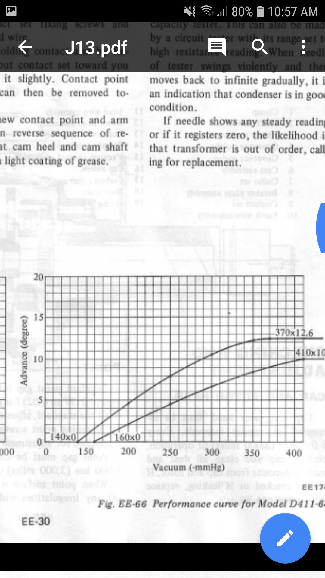
So, you have your basic "mechanical" curve plotted, and now you just need to add the vacuum-advance from Fig. EE-66 (above) to add the part-throttle engine load influence on ignition timing. Enter the significant values from the graph into the table, as +13° across 50kPa and below:
Vac_Adv_Add13_50kPa&Below.png
Vac_Adv_Add13_50kPa&Below.png (168.69 KiB) Viewed 10879 times
Then select the area from 50kPa to 80kPa (the active advance range) and interpolate vertically to blend the values between those two pressures:
Vac_Adv_InterpY_50-80kPa.png
Vac_Adv_InterpY_50-80kPa.png (158.04 KiB) Viewed 10879 times
While a number of added timing features can be added to this table that are not available or possible from a mechanical distributor; adding that vacuum-advance info onto your mechanical advance table produces this factory spec-equivalent table:
Mech+Vac Spk Tbl.png
Mech+Vac Spk Tbl.png (164.09 KiB) Viewed 10879 times

Other useful information from the manual: The factory carburetor was set-up with a power valve system that activated at 80 to 85kPa, to provide power AFRs. This is no coincidence, as the vacuum-advance begins to activate at 80kPa and below for economy. So, when making your initial AFR Table you would use rich AFR for power everywhere above 80kPa, lean AFR below that for economy, and tested idle AFR in the idle area. The AFRs will be found by testing for specific numbers, but initial targets may be 12.5 to 13:1 for power, 15.5 to 16.5:1 for economy, and whatever you find in initial idle tuning for the idle-area AFR.

While some carburetors use “ported vacuum”, the Datsun J13 does not appear to, from a quick scan of the manual. Ported vacuum is a special reduced vacuum (near atmospheric pressure) only when the carburetor is at low throttle (idle range) in order to limit the advance of the vacuum canister. This “ported” effect would make the idle advance substantially less, and would have been important to factory cars using it as an emissions control (sometimes just to reduce sharp exhaust odor) since the 1950s and even earlier. While it makes the engine less responsive when used, and also run hotter, it is a part of many factory emissions schemes. For other engines, be sure to check your manual for information that may alter your timing table further, especially around idle. For other factors such as engine temperature, timing corrections are available in Speeduino.

I hope that helps with one way to reproduce information in the factory service manuals into a Speeduino Spark Table, with complimentary initial target AFR ranges. It is only a place to begin tuning, and the tables will change to be more accurate and effective for your specific engine and fuel as your tune progresses. Have fun!

David
User avatar
By PSIG
#26852
Johndeer wrote: Fri Jul 06, 2018 2:53 pm This table need map sensor or not?
Yes.
PSIG wrote: Fri Jul 06, 2018 6:32 am... This example Spark Table uses Manifold Absolute Pressure (MAP) for load as the most commonly-used and recommended option for most performance and racing applications, but similar principles apply for tables using TPS or IMAP/EMAP for load estimation. ...
So, this table is designed for RPM vs MAP function, but could (with extensive testing) be altered to function with other load indicators. For example, the mechanical equivalent (RPM-only) portion would work directly for a TPS v RPM table, without the load (MAP) factors. Although the MAP factors could be used if altered by testing to find the equivalent TPS range similar loads and pressures are produced; with that much effort to modify it to work, it would likely be simpler and easier to crate a new overlay for TPS directly from testing.

Likewise, the mechanical advance alone would allow an engine converted from carburetor to ITB to be started and running for tuning; but would not be of much if any advantage over a simple RPM-only wedge table — and with marginally less effort. This again highlights why using shared information or tunes are not usually of particular advantage, especially on a different engine or fuel, or with altered/substituted components, setup or modifications. Either way the table will be different after tuning, and so it is your choice whether to begin with some reference values, or start from scratch with estimated or calculated values.
Image
David
User avatar
By V6vintage
#26855
Wow, thank you David. This post could not have arrived at a better time - today I 'inherited' an old AutoData book from 1978 which has lots of reference info for the ignition advance for my 1974 Ford Essex V6 engine; using this guide I made a spark table which runs pretty well!

If there is an appropriate section on the wiki I will have a go at uploading a screenshot / some numbers.

Thanks again!
User avatar
By PSIG
#26857
V6vintage wrote: Fri Jul 06, 2018 10:07 pmIf there is an appropriate section on the wiki I will have a go at uploading a screenshot / some numbers.
Once I get the section up on the Wiki, then it would be great to follow it with your example of real-world application with testing results. Thanks!

David

Always going to be one, I have completed 3 convers[…]

Do i have to do something in arduino software ? i […]

STM32 development

Not yet, I have been too busy to look into it but […]

Hola a todos Actualizo!!! Me es grato comunicaros[…]

Still can't find what you're looking for?