
- Thu May 27, 2021 3:04 am
#50581
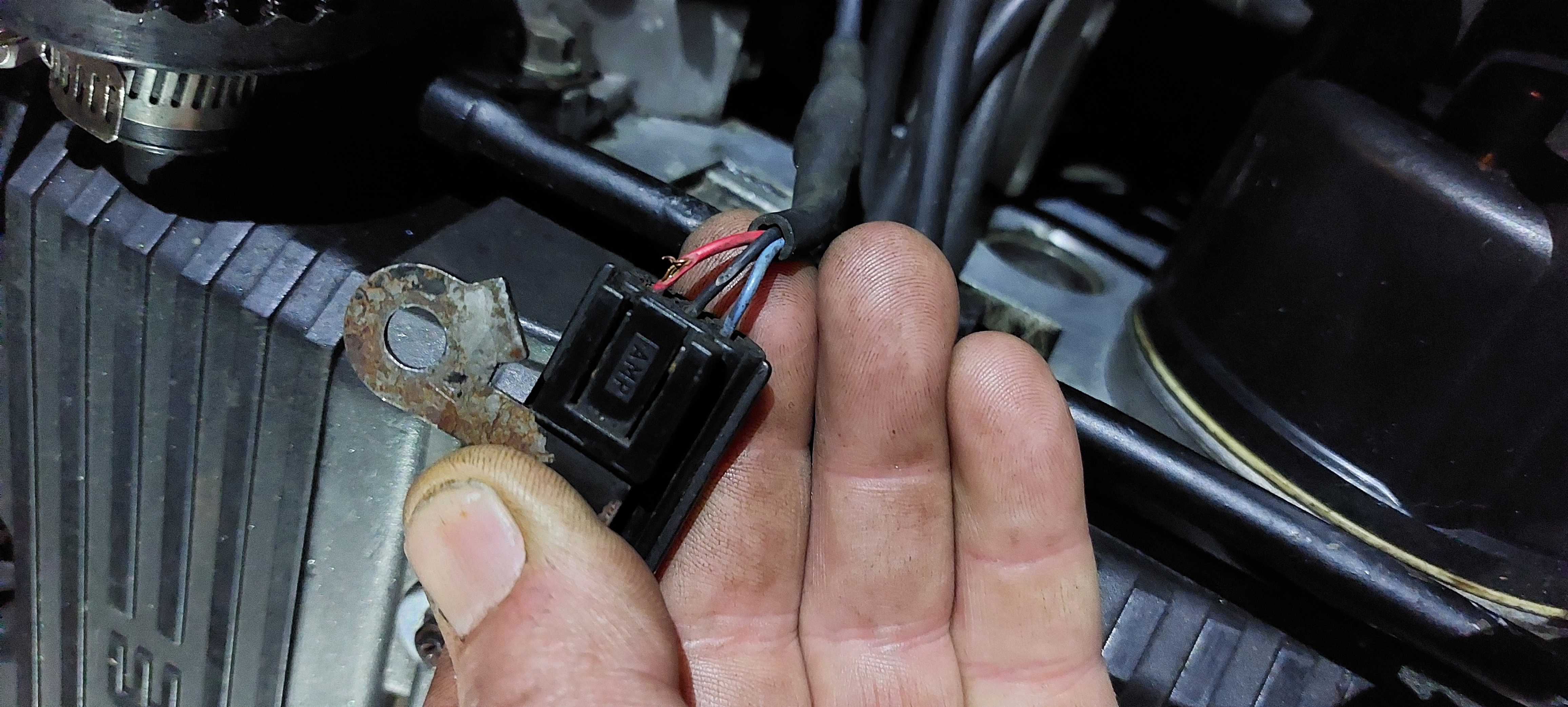 Cam sensor conn with 2signal and middle 0v re
20210527_025517.jpg (3.31 MiB) Viewed 5391 times
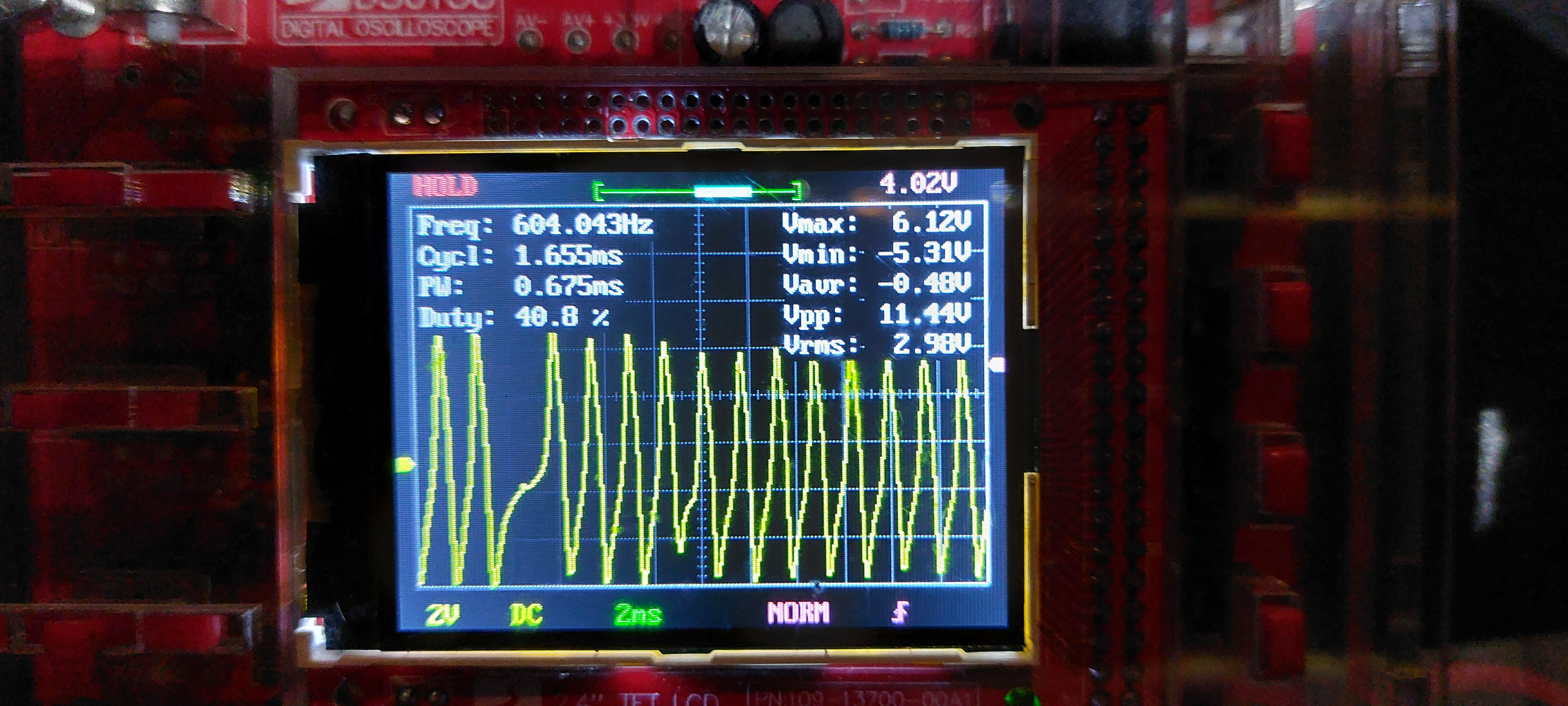 Crank signal 5v
20210527_033155.jpg (3.29 MiB) Viewed 5391 times
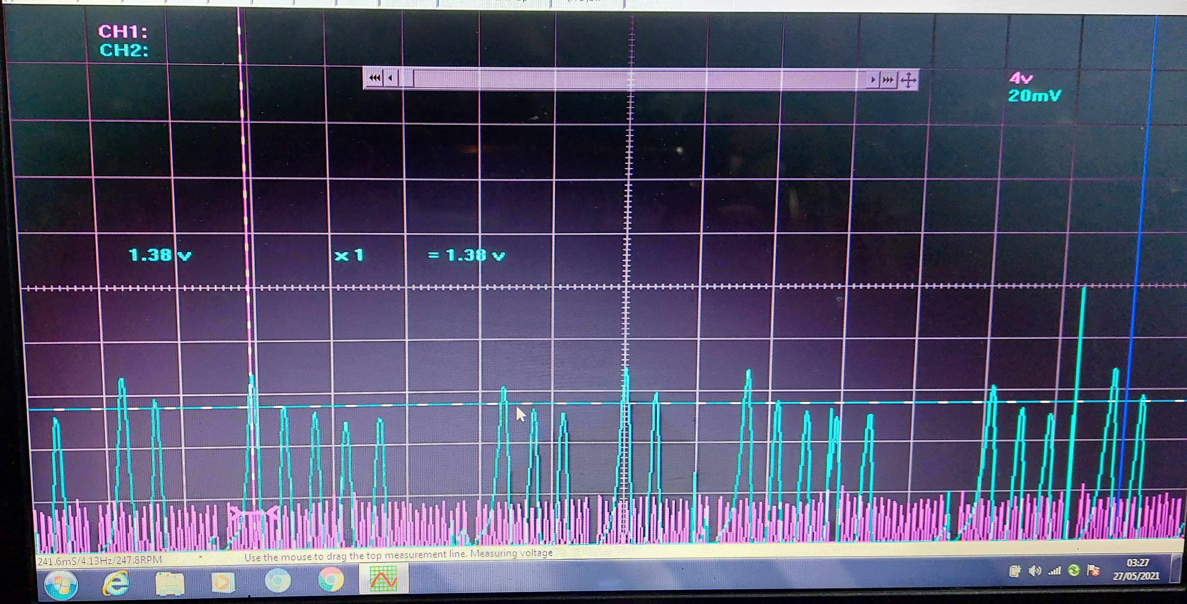 17g17g x2 for each cam 5g3g2g.
20210527_032718.jpg (2.84 MiB) Viewed 5391 times
So I am going through setting up a new feature elsewhere on the board getting new cam and crank combinations made up.
But this topic is some more general info I require.
So I am going to Include a picture of my cam and crank signal. There are 17 gap then 17gap twice on the crank for every cam rotation which has 5gap 3 gap then 2 gap on its rotation. This can be seen from the picture. This is expected.
What im not sure of. Is both sensors are 3 wire which I thought would be hall effect but both signals appear to be vr type. As they are not square waves.
My next question is the cam sensor is a good 5v signal which I've shown in a single channel picture. But the cam sensor is only about 1v or so.
My pic has crank at x10 on the lead to keep in same scale and picture. U can see cam looks bigger but its 0.1 the size at 1v peak not 5v. Hope this makes sense.
Is this normal? Maybe it's a vr type and the other 5v crank sensor a hall?
Both sensors have 3 wires.
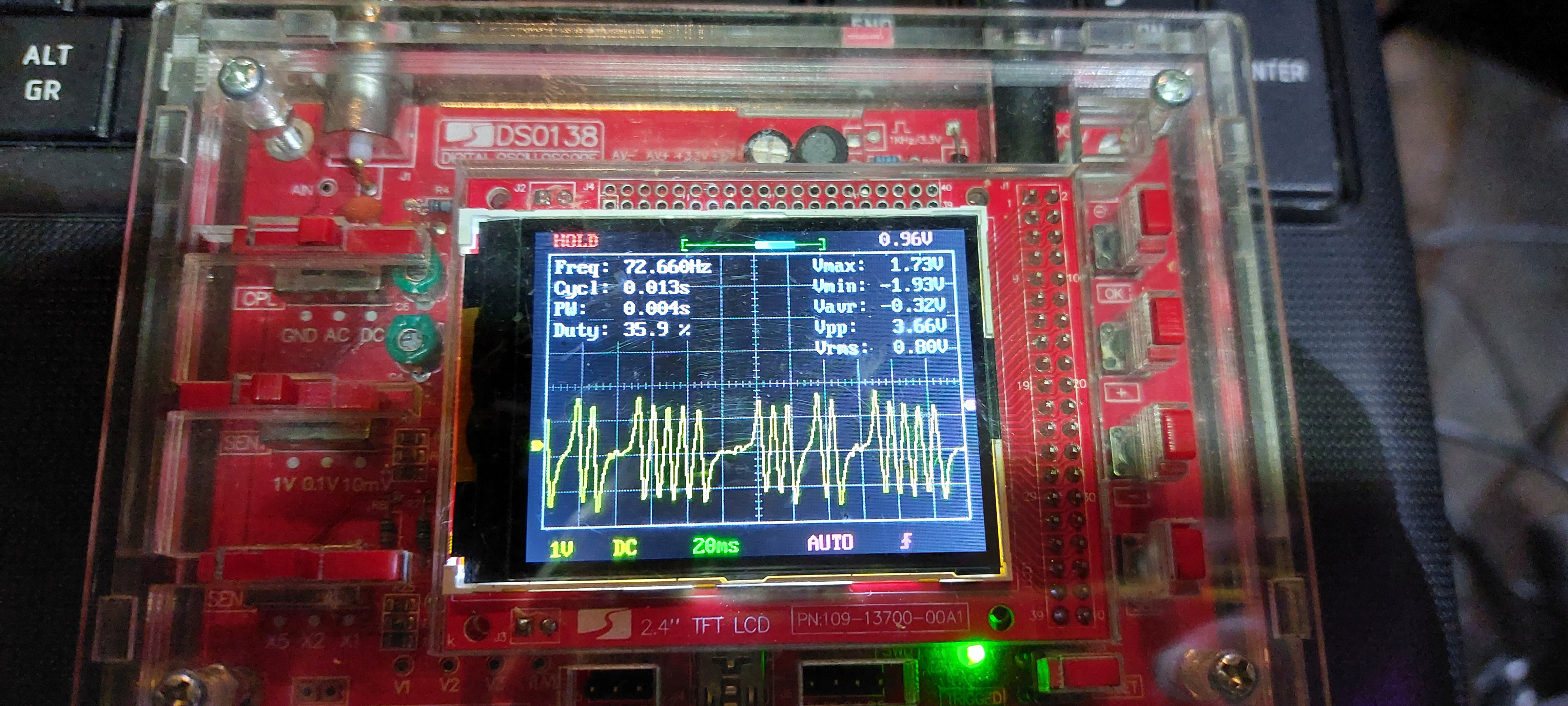 Cam signal 5g3g2g but only 1v
20210526_060826.jpg (2.79 MiB) Viewed 5391 times
The cam sensor has cam signal + a middle wire which appears to be ground and a signal wire -ve.
Is it normal to have a 3 wire sensor with middle wire ground?
Any help just covering this off would be great... many thanks. And I hope to be bringing nearly all the k series mg rover variants and the t series variants and testing them to allow speeduino to be used by the market over here which seems to be corners by emerald ecu which is the only standalone to cater for these types.
Open source all the way. thanks everyone here for making this possible....
But this topic is some more general info I require.
So I am going to Include a picture of my cam and crank signal. There are 17 gap then 17gap twice on the crank for every cam rotation which has 5gap 3 gap then 2 gap on its rotation. This can be seen from the picture. This is expected.
What im not sure of. Is both sensors are 3 wire which I thought would be hall effect but both signals appear to be vr type. As they are not square waves.
My next question is the cam sensor is a good 5v signal which I've shown in a single channel picture. But the cam sensor is only about 1v or so.
My pic has crank at x10 on the lead to keep in same scale and picture. U can see cam looks bigger but its 0.1 the size at 1v peak not 5v. Hope this makes sense.
Is this normal? Maybe it's a vr type and the other 5v crank sensor a hall?
Both sensors have 3 wires.
20210526_060826.jpg (2.79 MiB) Viewed 5391 times
Is it normal to have a 3 wire sensor with middle wire ground?
Any help just covering this off would be great... many thanks. And I hope to be bringing nearly all the k series mg rover variants and the t series variants and testing them to allow speeduino to be used by the market over here which seems to be corners by emerald ecu which is the only standalone to cater for these types.
Open source all the way.
Attachments
20210527_025517.jpg (3.31 MiB) Viewed 5391 times
20210527_033155.jpg (3.29 MiB) Viewed 5391 times
20210527_032718.jpg (2.84 MiB) Viewed 5391 times

 - By pazi88