Any questions you have before you begin buying, building and installing.
By crispy429
#51561
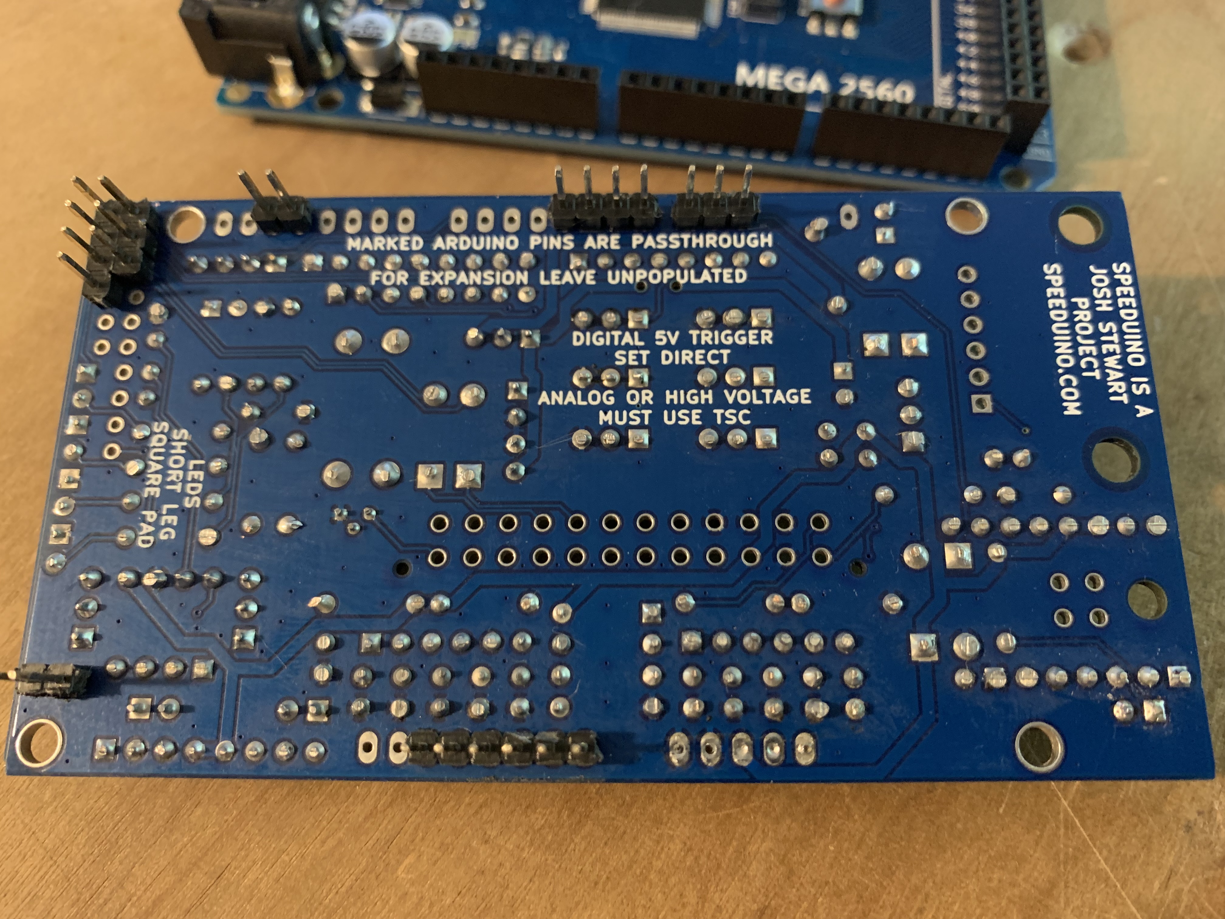
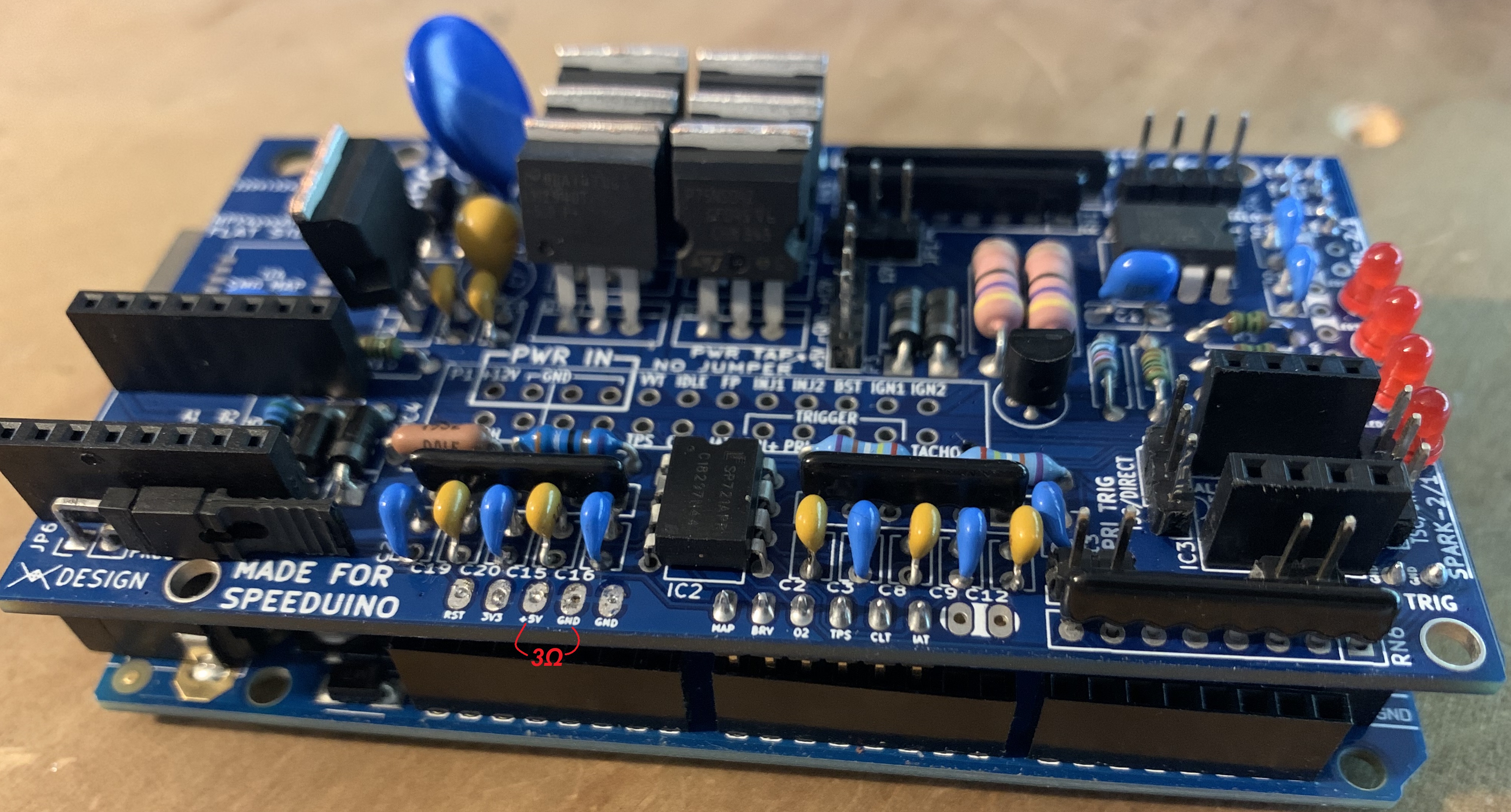
Hi guys, just received my NO2C and assembled it yesterday, but when I connect it to the Arduino, the Arduino dies (I have it attached to computer and connected to TunerStudio). If I connect it a few pins at a time, it doesn't die until the +5V pin on the bottom of the NO2C contacts the Arduino. I've measured a 3Ω resistance across the +5v to GND, which seems strange to me... This is less than any resistor (though possibly not the resistor network) and larger than a short. I removed these 5 jumper pins to see if there was a bridge underneath before discovering that the plastic slides up (so checked the other jumpers as well). My current thought is that this is low enough for the NO2C to short the +5v and take power away from the Arduino and shuts it off.

I've tried supplying +12v to the NO2C and +5v to the Arduino through USB and DC, same behavior. I've checked for shorts and can't find anything obvious or under the jumper plastic. Any ideas of what the problem might be or what I can try to rule some stuff out?

Thanks,
~Chris
Attachments
IMG_6582.JPG
IMG_6582.JPG (4.2 MiB) Viewed 3382 times
IMG_6581.JPG
IMG_6581.JPG (2.06 MiB) Viewed 3382 times
User avatar
By turboedge
#51568
I don't see any other soldering issues. other than the ground and 5v pins not being installed. Also the power regulator (the one by itself) will probably go into thermal shutdown with its tab removed like that. It needs to shed a fair amount of heat, but that's not the current issue. I'd suspect a diode in the wrong spot and/or incorrectly installed. Can we get some good top down pics?
By crispy429
#51570
There's a weird thing going on with the two lower left diodes, are they connected in opposite directions? All numbers in the photo are resistance measured with the positive lead at the labeled resistance location. I noticed that on those bottom left diodes, the resistance is the same at the bottom left and top right of that set, which made me think they were connected and allowing flow through the same path, but the resistance is so similar to the other 'cross' direction that I can't think of a reason to have diodes organized this way.

EDIT: Understood about the power regulator. I thought it was an IGBT and read that you could carefully cut the tabs off with no issues and I'd like lots of clearance as it's going in a bike. I'll try some thermal paste and a tiny heat sink on it and see if that does the trick.

EDIT2: Looking at the part numbers of the diodes, I think I have D3 and D4 mixed up, I'll try swapping them.
EDIT3: Swapped them, no difference... Dang.
Attachments
IMG_6584.JPG
IMG_6584.JPG (3.78 MiB) Viewed 3311 times
IMG_6583.JPG
IMG_6583.JPG (1.93 MiB) Viewed 3311 times
By crispy429
#51585
Is there a schematic available for the PCB that I can use to check which pins should and shouldn’t be conducting?

Can anyone do me a favor and measure the resistance between +5v and GND on a working board? I feel like these shouldn’t be connected by such a small resistance, I get 3ohm on mine…
By crispy429
#51696
Sorry, I should clarify - the USB cable setup I was using was insufficient. I have an extension from the computer to the front of my desk and a splitter with some keyboard/mouse dongles plugged in drawing some power, so the power was insufficient. I checked that this might be the cause back when the IGBT and power supply were swapped and it made no difference, but now with those corrected, plugging the Arduino directly to a USB port on the computer with nothing else drawing power works just fine.

Thanks!
~Chris

nice first of all, i read all that crap months a[…]

I rewired a few grounds and tested the TPS and rel[…]

Thanks, car runs great now !!! Going to drift even[…]

sauver moteur v8

bonsoir je m appel jean marie et j habite en Franc[…]

Still can't find what you're looking for?