
- Fri Jan 11, 2019 11:42 pm
#31175
 trigger wheel, when #1 tooth passes sensor
10 no. 1 tooth passing sensor angle.JPG (277.98 KiB) Viewed 8586 times
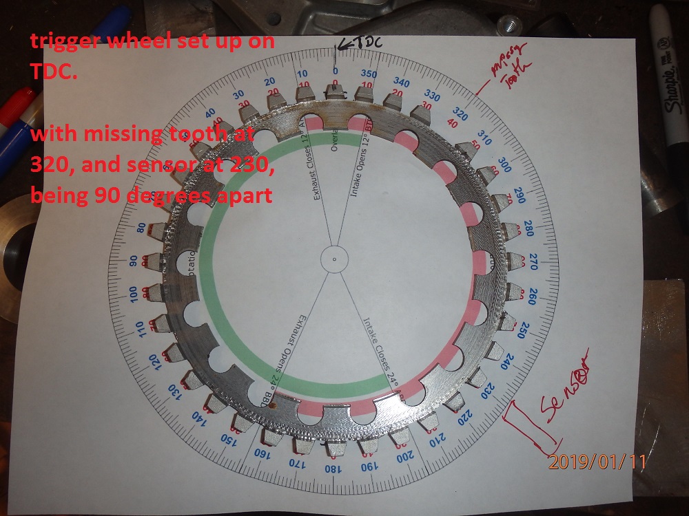 trigger wheel at TDC
9 tigger wheel at TDC.JPG (240.48 KiB) Viewed 8586 times
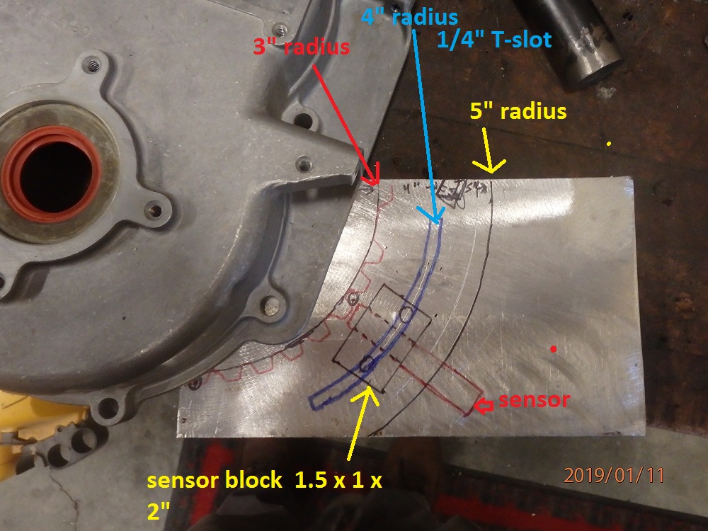 crankshaft sensor bracket
07 final location .JPG (251.11 KiB) Viewed 8586 times
in fabbing a bracket for the crankshaft sensor, to go on my stand-alone 4A084 motor, I am asking to see if I got this figured out somewhat correctly.
from what i am finding out the sensor needs to be mounted 90 degrees before the missing tooth.
with the style of bracket that i am making it should give a an option to move the sensor up to 20 degrees if needed.
in the trigger set up module. it states that the trigger angle is the angle ATDC when tooth #1 passes the primary sensor..
from what i am understanding from this, the #1 tooth will be passing the sensor at 130 degrees ATDC.
am i correct in this thinking?
then i get to move on to the spark plug settings
from what i understand, with the motor timing set to fire at 28 BTDC.
I set both the Cranking advance & fixed angle to 28,
below are pictures of the base bracket i will be making, using a T-slot, so the sensor can be adjusted. along with the trigger tooth wheel on a degree chart. along with the trigger wheel placed on a degree wheel to help with trying to understand this setup.
Attachments
10 no. 1 tooth passing sensor angle.JPG (277.98 KiB) Viewed 8586 times
9 tigger wheel at TDC.JPG (240.48 KiB) Viewed 8586 times
07 final location .JPG (251.11 KiB) Viewed 8586 times
