For discussion of Speeduino compatible boards designed / built by other members of the forum and for guidance around making such a board
User avatar
By jbiplane
#46769
joey120373 wrote: Sun Nov 29, 2020 2:04 pm The current board has most of the features of a standard speeduino board, 4 injector drivers, stepper controller etc, plus it also has 4 ignition IGBTs on board because 3 of my projects do not have a separate ignition module.
So, that being the case, it could be made much smaller by getting rid of a lot of that stuff.
Hi Joe. Your project look nice and seems very good starting point.
- It seems the most unnesesary option is stepper controller which take 4 wires.
- 4 injector and 4 ignition IGBTs possible remain and schematic to have one universal board
and place 1,2,3 or 4 channels
- I want place on board contactless magnetic TPS
- IAT as well could be on PCB
By joey120373
#46773
4 IGBTs is probably overkill, and they take up a lot of space. 2 IGBT channels would run 4cylinders in waisted spark mode. That would cover 99% of all small engines.

Magnetic TPS is interesting.

I’ll start modifying the schematic and the board as time permits. The current design uses 2 max 9924 VR interfaces, the primary Is configurable to operate in either mode A2 ( adaptive input threshold ) or mode B, (with zero crossing but without adaptive threshold).
I think this is important as the adaptive threshold feature might not be wanted on single and dual cylinder applications.

What dimensions are you shooting for?
By joey120373
#46775
Another pic with components. There is nothing on the back side save some jumpers configure the VR inputs and a few of the ADC inputs
Attachments
C98D1BFD-EF57-459F-9DA7-70517E38FA46.jpeg
C98D1BFD-EF57-459F-9DA7-70517E38FA46.jpeg (1.63 MiB) Viewed 8774 times
User avatar
By jbiplane
#46792
joey120373 wrote: Sun Nov 29, 2020 7:49 pm Another pic with components. There is nothing on the back side save some jumpers configure the VR inputs and a few of the ADC inputs
Looks rational. Can you please show back side to understand if it possible place marnetic position sensor, says AS5600 on back side of PCB approx in the center? Would it possible to make simple modifications of existing board to have it tested?
Dont rework it from scratch.

Can we place IAT in "cold" place of board? It can be located at PCB center line up or down TPS

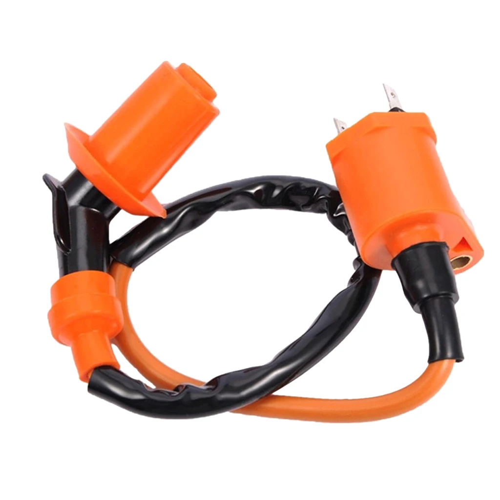
What small sized ignition coil will work nicelly driven by your board?
Says will it work with GY6 small coil like this?
Image

>What dimensions are you shooting for?
60x60+- absolutelly fit most of uses
By fram
#46796
HI Joey

It seems you're gonna use BLE 4.0 module into your PCB.
I'm currently under test at the moment with my board and HM-11 BLE module, and i cannot communicate with both windows or android. So, no com with TS or others android apps.

The issue is with the BLE 4.0, you don't have the virtual COM port under windows, and under android you cannot pair easily.
You need to go for SPP bluetooth module (Serial Port Protocol) so, I'm on my way to switch to Bluetooth 2.0/3.0 module (JDY-30)
;)
By joey120373
#46823
Hmm, I was targeting my iPhone when I decided on that module, I have an hm11 and an hm19 to play with, I’ll have to wire them up and see what results I get. If those don’t play nice with TS on IOS I’ll have to see about a HC05/6, might have to put the footprint on the back of the board.

Speaking of the back, I’ll try to load a pic in the next day or two, right now I am out in the middle of nowhere for work. But the backside of the board is all ground fill, no traces, and about 6 solder jumpers. So there is plenty of room for a hall type sensor. What IC did you have in mind? To keep it simple it will need an analog output.
User avatar
By jbiplane
#46826
Hi Joe
joey120373 wrote: Tue Dec 01, 2020 3:53 pm 1. I’ll have to see about a HC05/6, might have to put the footprint on the back of the board.

2. the backside of the board is all ground fill, no traces, and about 6 solder jumpers. So there is plenty of room
1. HC05 is more featured than HC06. It can be made detachable.
Seems it is rational to to have on board just UART and connect one of USB, Bluetooth classic, Wifi... as required

2. Instead of external TPC at moment we are trying to use AS5600 magnetic position sensor.
https://www.digikey.com/en/ptm/a/ams/as ... ion-sensor
https://eu.mouser.com/new/ams/ams-as5600-sensor/
Seems it can be placed on "back" of you PCB
Image

Some other ideas
https://www.roboticsbusinessreview.com/ ... ot-design/
User avatar
By jbiplane
#46835
We in process of make our ECU integrating to throttle body,
but cannot make it Open Source (project paid by customer)

Wiring, max 20:
CLT - cooling liquid temperature, can be used for air cooling as well
Al + CHR thermocouple type k to be fitter under spark of one cylinder which is in worst conditions
O2 - narrow band lambda
2 ignition channels
2 injections channels
2 wires for Crankshaft sensor
2 wires for Camshaft sensor
R-in programmable to fill any resistive sensor, can be switched to V sensing, says for exhaust temperature control using AD595
IAC - idle control
FP and FPM fuel pump and fuel pump modulation to minimize electricity consumption on small engines
3 wires ground (power, ignition, sensors)
2 grounds
1 +12V power supply


Minimal wires count could be 8 (max 20)

1 ignition channel
1 injections channel
2 wires for Crankshaft sensor
FP and FPM fuel pump and fuel pump modulation to minimize electricity consumption on small engines
3 grounds
1 +12V power supply

One day we will make simular project based on open source Speeduino
Last edited by jbiplane on Mon Dec 14, 2020 3:58 am, edited 1 time in total.
By dazq
#46839
jbiplane wrote: Wed Dec 02, 2020 4:35 am We in process of make our ECU integrating to throttle body,
but cannot make it Open Source (project paid by customer)
Image

Wiring, max 20:
CLT - cooling liquid temperature, can be used for air cooling as well
Al + CHR thermocouple type k to be fitter under spark of one cylinder which is in worst conditions
O2 - narrow band lambda
2 ignition channels
2 injections channels
2 wires for Crankshaft sensor
2 wires for Camshaft sensor
R-in programmable to fill any resistive sensor, can be switched to V sensing, says for exhaust temperature control using AD595
IAC - idle control
FP and FPM fuel pump and fuel pump modulation to minimize electricity consumption on small engines
3 wires ground (power, ignition, sensors)
2 grounds
1 +12V power supply


Minimal wires count could be 8 (max 20)

1 ignition channel
1 injections channel
2 wires for Crankshaft sensor
FP and FPM fuel pump and fuel pump modulation to minimize electricity consumption on small engines
3 grounds
1 +12V power supply

One day we will make simular project based on open source Speeduino
Do you intend to run your board on speeduino firmware/code?
I you do you had better speak with Josh( noisymime ) about licensing agreement if you cannot make the board open source.
User avatar
By jbiplane
#46840
The board on photo use processor which designed and made in Russia. Exotic for remaining market.

I want to make simular sized PCB, but open source, based on Speeduino or may be RusEFI. Estimating at moment.
MAP LOOKUP & TS DEFINITIONS

See how the write commands use the identifiers to […]

Ok, I feel so stupid. I was running the Uno output[…]

Let's all have a laugh for second. There's trash[…]

It has been done more than a few times, there was […]

Still can't find what you're looking for?