

- Fri Jan 19, 2018 12:53 am
#23763
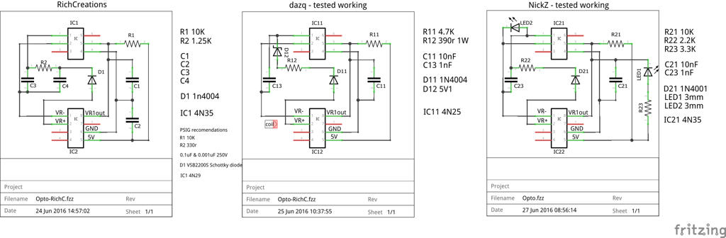
Those are diagnostic LED indicators. LED1 is on if the board has power. LED2 flashes when a signal is passed. At cranking or low speeds, you can see the flashes, but at higher rpm, it just looks brighter 'on'. Below is my prototype of the SSC (Single Signal Conditioner) for VR/Hall/Opto showing the LED flash when a trigger signal is passed to Speeduino. If you see flashes the board is working, but if you then see no rpm, then the problem is on the Speeduino board, or tune settings. Diagnostics.
David
This old and crappy video was to show the extremely low rpm sensing of the SSC prototype directly from a distributor VR sensor (not through the factory module), which are normally difficult to read at very low rpm. The diagnostic LED shows the signals for each cylinder are being processed and sent to Speeduino which become a blur quite rapidly as rpm rise (click link if it does not appear here):http://efistuff.orgfree.com/PostHost/VR ... R-v1FR.mp4
http://efistuff.orgfree.com/PostHost/VR_Module_H-VR-v1FR.mp4
Last edited by PSIG on Sun Feb 25, 2018 6:39 pm, edited 3 times in total.
-= If it was easy, everyone would do it =-

 - By pazi88