For any add-on boards such as VR conditioners, optos and OEM interface boards
User avatar
By DStage
#53484
Hi there!

I thought I'll share a project of mine - an electronic throttle controller. I've been using first revision for over 5 years now and it has never failed me so I think I can say it's pretty reliable and robust ;-)

The board is purely analogue, no programming required and no chance of failure due to MCU hang-up, flash disappearing due to harsh engine environment etc. Safety was my priority with this one ;-) It also has build in simple fail safes - in case any of the control wires is broken or shorted with power for example the throttle will close automatically.

I was planning to put it on github but never found time so maybe I'll just start here :lol: I attached unfinished documentation and gerber files for new revision. The difference on this one is in IAC input. Previously I forgot to take into account the fail safes and as a result only about upper 30% of PWM was usable. This new one fixes this issue.

The board shape is designed to fit popular aluminium casing to be found in tme.eu, Farnell etc. There are no connectors, wires are soldered directly to the board to keep it compact.

You can also check a video of mine where I talk some more about this project: https://www.youtube.com/watch?v=MTnsbOgZkUA

UPDATE 2022.01.04:
I have created a github repository: https://github.com/DStageGarage/Electro ... ontroller

UPDATE 2022.12.13:
Please use the files from v1.3 folder on repo. You will also find a detailed description of ordering process from JLCPCB in chapter 3 of the new manual.

UPDATE 2022.12.30:
There is now v1.4 beta described on page 9 of this thread.
Attachments
ETC v1.1 render top.PNG
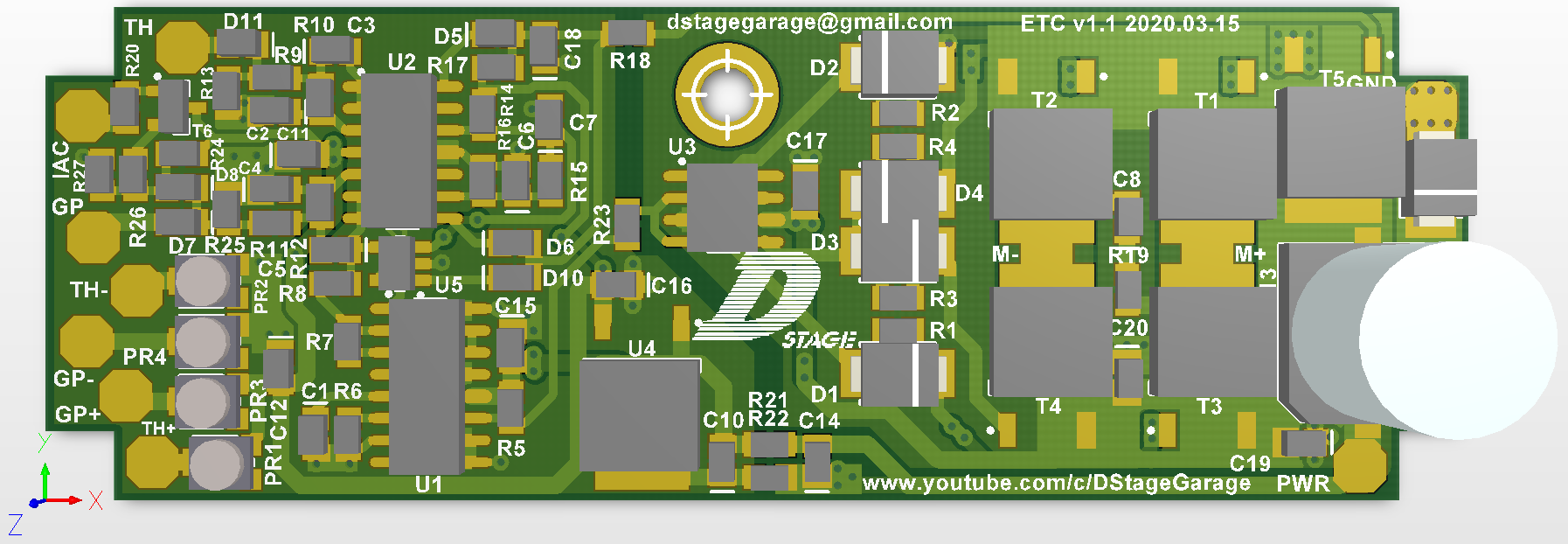
ETC v1.1 render top.PNG (390.51 KiB) Viewed 27909 times
(183.88 KiB) Downloaded 1469 times
Last edited by DStage on Fri Dec 30, 2022 11:44 pm, edited 4 times in total.
#53809
I've been thinking about making something like this myself, but you already have so thanks for publishing it. Question about the potentiometers, if I understand correctly the GP+ GP- TH+ TH- are to compensate for safety offset. Is there any way to use this with a throttlebody that uses HAL effect sensors where you cannot set an offset like this?
User avatar
By DStage
#53998
digmorepaka wrote: Tue Nov 02, 2021 8:58 am I've been thinking about making something like this myself, but you already have so thanks for publishing it. Question about the potentiometers, if I understand correctly the GP+ GP- TH+ TH- are to compensate for safety offset. Is there any way to use this with a throttlebody that uses HAL effect sensors where you cannot set an offset like this?
Sorry for late reply. I was thinking about such use case as I have a Golf V gas pedal lying around that uses magnetic fields (it's not HALL based I think but same kind of problem). Just out of curiosity where did you find throttle body with HALL sensors? I just though most cars use Bosch, although probably not in US ;-)
Anyway, I was planning to include stuff like that into the documentation if and when I will finalize it :lol: The easiest solution is to not use the safety feature for example by removing D5, D6 and D10. Another option is to utilize the fact that at least in some cases (that is for example the case with this Golf gas pedal) the voltage range at gas/throttle output is not going from 0 to 5V but is restricted somewhat on both sides. Then if you have such hall or other non potentiometer based thing on one side and use a potentiometer on the other you can still set it the same range and just change values of R14/15/16 if needed to account for that. I think usually there will be two voltage outputs and there's a chance that at least one of those has such limited range.
#54002
DStage wrote: Wed Nov 17, 2021 5:06 pm
digmorepaka wrote: Tue Nov 02, 2021 8:58 am I've been thinking about making something like this myself, but you already have so thanks for publishing it. Question about the potentiometers, if I understand correctly the GP+ GP- TH+ TH- are to compensate for safety offset. Is there any way to use this with a throttlebody that uses HAL effect sensors where you cannot set an offset like this?
Sorry for late reply. I was thinking about such use case as I have a Golf V gas pedal lying around that uses magnetic fields (it's not HALL based I think but same kind of problem). Just out of curiosity where did you find throttle body with HALL sensors? I just though most cars use Bosch, although probably not in US ;-)
Anyway, I was planning to include stuff like that into the documentation if and when I will finalize it :lol: The easiest solution is to not use the safety feature for example by removing D5, D6 and D10. Another option is to utilize the fact that at least in some cases (that is for example the case with this Golf gas pedal) the voltage range at gas/throttle output is not going from 0 to 5V but is restricted somewhat on both sides. Then if you have such hall or other non potentiometer based thing on one side and use a potentiometer on the other you can still set it the same range and just change values of R14/15/16 if needed to account for that. I think usually there will be two voltage outputs and there's a chance that at least one of those has such limited range.
I found the throttlebody in a OBDII Corolla Verso with the 1ZZ. I believe the T23 DBW celicas should have this too. I found it weird that it only used a HAL throttlebody, but a potentiometer pedal, both are denso parts i believe. Here's a couple snippets from the service manual

Image
Image
Image
Image
User avatar
By DStage
#54274
digmorepaka wrote: Fri Nov 19, 2021 3:38 pm I found the throttlebody in a OBDII Corolla Verso with the 1ZZ. I believe the T23 DBW celicas should have this too. I found it weird that it only used a HAL throttlebody, but a potentiometer pedal, both are denso parts i believe. Here's a couple snippets from the service manual
I think you've hit the jackpot, that's pretty much all you need to make it work. And looking at those plots it seems it should work. Since the gas pedal looks to be resistive (pot based) I's suggest to tweak it's output voltages a bit (with the trip pots on my controller) to match those of one of the characteristics of the throttle body. It shouldn't be too complex. VTA1 seems better candidate as VTA2 seems to saturate before the throttle is fully open. I would suggest to measure the VTA1 with throttle fully open (just move it manually without the motor connected) and if it's below 4-4.1V you can tweak the voltage divider for fail safes on the controller to move the upper voltage within 0.1-0.2V above the fully opened throttle level at VTA1. Just in case you could also do the same with the closed position and if needed change a bit the lower safety threshold which by default is set to 0.8V. Drop me a line on dstagegarage@gmail.com if you need help with that.
User avatar
By DStage
#54449
I attach gerbers for V1.2. Thanks to one colleague who really wants to manufacture and assembly it in JLCPCB I've moved it a bit further ;-)
The only difference in PCB is that I've moved D3, D4 and R1-4 slightly so they are farther apart as JLC might complain about the previous version.

The rar now also contains pick and place files. I have also prepared a new BOM in format described in JLC FAQ that also includes part IDs from their catalogue. This may change as many of the parts like resistors have plenty alternatives so maybe for whatever reason it's better to choose a different one. There was a bit of a pain in finding a proper electrolytic cap so in the end it's of lower capacity but still has a proper voltage and low impedance so I think it should do. Also at the moment they are out of stock with TC4428 (TC4425 as well). The BOM is refreshed every now and then on my google drive so if anyone is interested I can provide an access. For now I attach it here.

Edit - seems I cannot attach files ase there's some space limit issue. Please email me if you're interested in getting those.
#54462
DStage wrote: Tue Dec 28, 2021 1:56 am I attach gerbers for V1.2. Thanks to one colleague who really wants to manufacture and assembly it in JLCPCB I've moved it a bit further ;-)
The only difference in PCB is that I've moved D3, D4 and R1-4 slightly so they are farther apart as JLC might complain about the previous version.

The rar now also contains pick and place files. I have also prepared a new BOM in format described in JLC FAQ that also includes part IDs from their catalogue. This may change as many of the parts like resistors have plenty alternatives so maybe for whatever reason it's better to choose a different one. There was a bit of a pain in finding a proper electrolytic cap so in the end it's of lower capacity but still has a proper voltage and low impedance so I think it should do. Also at the moment they are out of stock with TC4428 (TC4425 as well). The BOM is refreshed every now and then on my google drive so if anyone is interested I can provide an access. For now I attach it here.

Edit - seems I cannot attach files ase there's some space limit issue. Please email me if you're interested in getting those.

I'm interested, you have a private message.
Thanks
#54505
DStage wrote: Tue Dec 28, 2021 1:56 am seems I cannot attach files ase there's some space limit issue. Please email me if you're interested in getting those.
Would be awesome if you could upload the production and source files to a site like github, that way they would be very accessible and no need to deal with sketchy hosting sites or P2P over email sharing.
  • 1
  • 2
  • 3
  • 4
  • 5
  • 12
Ignition Angle doubled?

I just erased the flash, went back to 2023-10, cre[…]

Doesn't look like you can edit posts? Correct. […]

BMW E23 M30B28

Don't forget, you can always fall-back to the &[…]

The basetunes were on so old version that they did[…]

Still can't find what you're looking for?