For any add-on boards such as VR conditioners, optos and OEM interface boards
By ironmanisanemic
#38641
jonbill wrote: Sun Oct 13, 2019 9:10 pm Hi, a bump for this thread and kit. I installed it this weekend on my Speeduino and car and I'm very happy. Especially like the fact that the pins can be unlocked and removed from the plug without special tools since I'll be replacing the TPS and adding injection and more sensors in the coming months.

Only trouble I had was the wires for the vr sensor proved a little hard to get into the plug, mainly down to my crimping tool and technique I'm sure.
Thanks @ironmanisanemic
Thank you for the kind words! Im quite glad you enjoy the unit.
evo_lucian wrote:Love the idea. Do you have any updated pics ?
No, i do not. My project vehicle has been put on hold for the moment.

I have created a cover to protect the pins of the connector. it is still very much a work in process, but it should do the trick. i still have to add a hole for the Map passthrough, but a drill bit will also do the trick.

Once thingiverse lets me publish the STL i will update with a download link.


EDIT:
Here is the thingiverse link: https://www.thingiverse.com/thing:3923271
Attachments
Speeduino cover.jpg
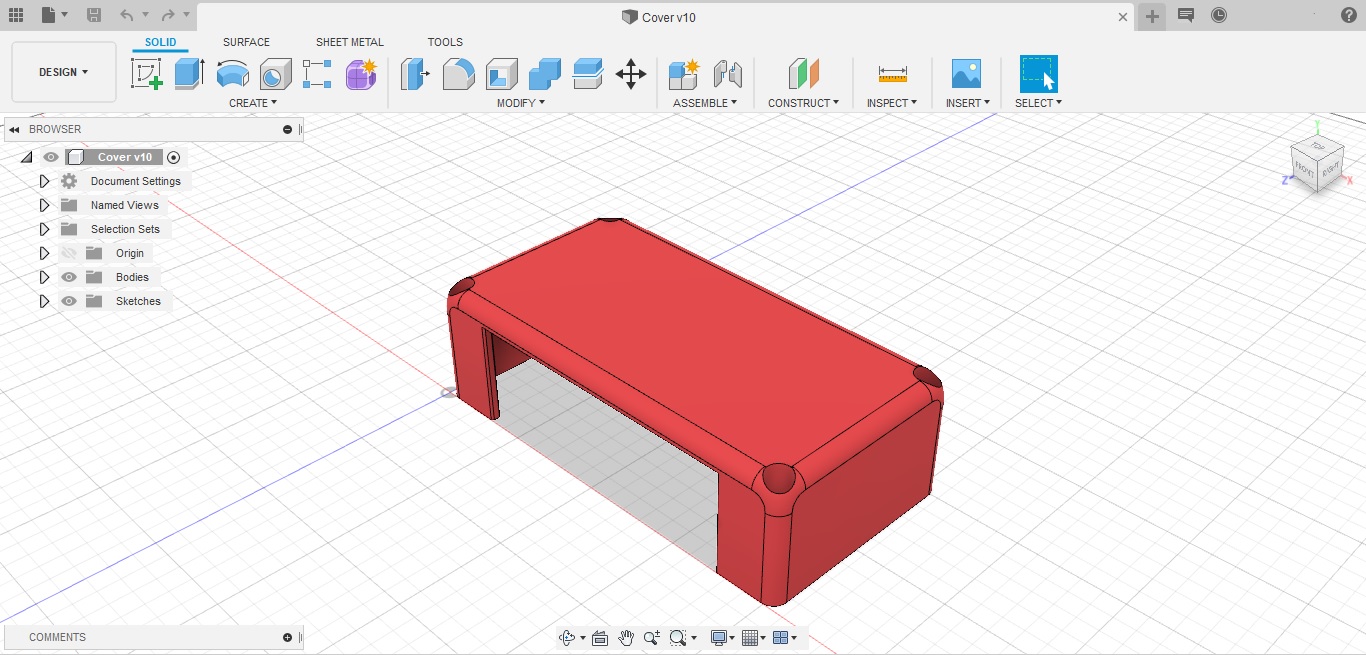
Speeduino cover.jpg (248.63 KiB) Viewed 10689 times
Last edited by ironmanisanemic on Sat Oct 19, 2019 3:42 pm, edited 1 time in total.
User avatar
By PSIG
#38657
ironmanisanemic wrote: Fri Oct 18, 2019 9:17 pm Once thingiverse lets me publish the STL i will update with a download link.
In order to maintain availability, I would suggest posting the STL here, and then also a Thingverse link when you have it. This keeps everything a user needs in one place, and if the Tv link ever dies, it's still here. ;)

David
By ironmanisanemic
#38661
PSIG wrote: Sat Oct 19, 2019 1:45 pm
ironmanisanemic wrote: Fri Oct 18, 2019 9:17 pm Once thingiverse lets me publish the STL i will update with a download link.
In order to maintain availability, I would suggest posting the STL here, and then also a Thingverse link when you have it. This keeps everything a user needs in one place, and if the Tv link ever dies, it's still here. ;)

David
I tried to post the stl, but it said invalid file extension. So I guess I will have to zip the file to post it up.

EDIT:
Attached STL file.

EDIT 2:
Cover has been redesigned, see post below for new stl file.
Attachments
Old Version, dont use.
(74 KiB) Downloaded 410 times
By ironmanisanemic
#44344
Wow, a lot has happened since the last time i made any updates on this. I moved, bought a home, went on a cross country trip in the midst of a global pandemic. Anyway, i finally had some time to do some much needed changes to the cover i designed. First, i realized after unpacking my 3d printer and making the part that i made the cutout much to large. Also, needed to adjust the mounting screw hole sizes as well. I also decided to add some sort of mounting system. I am going to design a matching back cover to give rear mounts as well.

The PCB is going to have to be redesigned. I am going to have to migrate to Kicad from EasyEDA, because it has better cad tools, and can more easily move designs from kicad to fusion 360 and vice versa.

This cover works with the current version of the board and should be forward compatible with later revisions. Im using M4x30 screw cap bolts to secure everything together.
Attachments
(70.09 KiB) Downloaded 370 times
IMG_20200720_151526.jpg
IMG_20200720_151526.jpg (3.45 MiB) Viewed 9254 times
IMG_20200720_151521.jpg
IMG_20200720_151521.jpg (3.84 MiB) Viewed 9254 times
speeduino cover v2.png
speeduino cover v2.png (330.58 KiB) Viewed 9254 times
Last edited by ironmanisanemic on Tue Jul 21, 2020 4:25 am, edited 1 time in total.
By ironmanisanemic
#44346
As promised i have made the rear cover with integrated mount just like the front. this should make mounting the ecu into tight spaces easier.

I am currently printing the newest versions. I will upload photos once they are completed and installed.
Attachments
(47.87 KiB) Downloaded 368 times
speeduino cover rear v2.png
speeduino cover rear v2.png (315.55 KiB) Viewed 9243 times
By ironmanisanemic
#44369
Need to get hardware for the rear cover, but here are the new designs fresh off the printer.
Attachments
IMG_20200721_062310.jpg
IMG_20200721_062310.jpg (3.92 MiB) Viewed 9213 times
IMG_20200721_062304.jpg
IMG_20200721_062304.jpg (4.41 MiB) Viewed 9213 times
IMG_20200721_062249.jpg
IMG_20200721_062249.jpg (4.34 MiB) Viewed 9213 times
By Gshorten
#45479
Great Idea, thanks for designing this!! I ordered the parts below from Digikey, it is a great connector. However the part number for the small pins is incorrect, see the molex data sheet https://www.molex.com/pdm_docs/sd/643201311_sd.pdf
There are 3 different sizes of pins for the 0.6 mm connections, and two different sizes for the 1.5mm connections, depending on your wire thickness. I ordered some of each, they are only ~$0.35 each. These are all tin plated, apparently you have to order 65,000 pcs to get gold plated :-(

Part numbers for the small pins (cp 0.6)
wire insulation dia 1.25 to 1.4mm : 0643221019 (this should cover most signal and sensor wires)
wire insulation dia 1.4mm to 1.7mm: 0643221039
wire insulation dia 1.6mm to 1.9mm: 0643221039

For the 6 large pins , power and injectors (cp 1.5):
wire insulation dia 1.4mm to 2.15mm: 0643231029
wire insulation dia 2.1 to 2.8mm: 0643231039 (this is what I used for my injectors, pwr, ground wires)

Blind plugs:
0.6mm pins: 0643251010
1.5mm pins: 0343251023
Molex says that blind plugs must be used in unused holes, presumably this is for weather sealing

If you need to remove pins you'll need an extraction tool, I got a set on amazon for about $10
ironmanisanemic wrote: Tue Jul 23, 2019 2:49 am I figured i would post up the part numbers for the Molex connector and its matching pins and housing as well as the rest of the parts to finish out this board. That way if anyone else is interested in making this board, they arent left scratching their heads looking for the right part numbers.

PCB CONNECTOR HEADER - MOLEX - 5007620481
CONNECTOR RECEPTICLE - MOLEX - 0643201311
WIRE BACK SHELL - MOLEX - 0643201301
BLIND PLUGS - MOLEX - 0643251010 (ONLY NEED 10 OF THESE, BUT GET EXTRA)
14-16AWG TERMINAL - MOLEX - 0643231039 (ONLY NEED 6 OF THESE, BUT GET EXTRA)
18-20AWG TERMINAL - MOLEX - 0643231029 (ONLY NEED 32 OF THESE, BUT GET EXTRA)
40 POSITION HEADER - 3M - 30340-6002HB
2 POS TERMINAL BLOCK - PHOENIX - 1935161

All parts can be purchased from DigiKey, Mouser, Etc... Board can be ordered with the attached gerber files from any board house of your choosing, or from JLCPCB using the link in the first post.

The IDC/Dupont cable is a custom length cable that i made. I sourced the parts locally from an electronics surplus store, so i do not have part numbers at the moment. Next time i am down there i will grab them to add to my BOM.

Also, attached is the current pinout.

nice first of all, i read all that crap months a[…]

I rewired a few grounds and tested the TPS and rel[…]

Thanks, car runs great now !!! Going to drift even[…]

sauver moteur v8

bonsoir je m appel jean marie et j habite en Franc[…]

Still can't find what you're looking for?