
- Fri Aug 14, 2020 7:28 pm
#44728
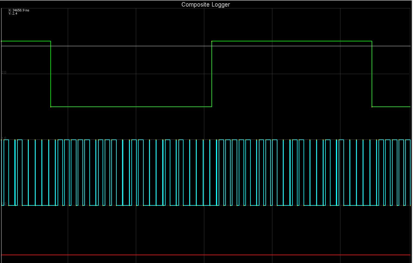 trigger.JPG (119.65 KiB) Viewed 4636 times
I have a LS engine with a 24 tooth stock crank wheel and a 2 tooth cam wheel.
For some strange reason the GM 24x pattern runs really rough and backfires, but if I use dual wheel 24 tooth and both on falling edge it runs great, but it shouldn't.
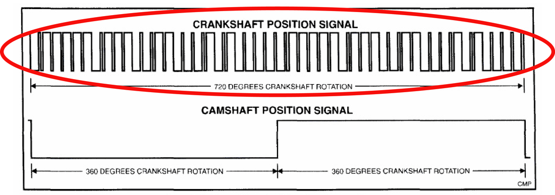
I have it set at 24 tooth and both are falling trigger, so based on the diagram it should fail sync should it not?
Looking at the diagram 48 teeth would pass between the 2 cam falling edges?
So it acts like the cam trigger is using BOTH for a setting, but I can't find anything in the code that would allow this.
But the GM 24x trigger setting uses BOTH for the cam and it doesn't run good at all so I am a little confused here.
I would think the dual wheel setting with 24 teeth and falling edge would give a constant stream of failed sync counts, but it doesn't for some reason.
Attached is a log and image of my trigger
Just looking for some insight on why this is working as it is.
For some strange reason the GM 24x pattern runs really rough and backfires, but if I use dual wheel 24 tooth and both on falling edge it runs great, but it shouldn't.
I have it set at 24 tooth and both are falling trigger, so based on the diagram it should fail sync should it not?
Looking at the diagram 48 teeth would pass between the 2 cam falling edges?
So it acts like the cam trigger is using BOTH for a setting, but I can't find anything in the code that would allow this.
But the GM 24x trigger setting uses BOTH for the cam and it doesn't run good at all so I am a little confused here.
I would think the dual wheel setting with 24 teeth and falling edge would give a constant stream of failed sync counts, but it doesn't for some reason.
Attached is a log and image of my trigger
Just looking for some insight on why this is working as it is.
Attachments
(74.96 KiB) Downloaded 246 times

