For anything you'd like to see added to Speeduino
User avatar
By kimdrummel
#7620
I have now conducted some testing with the MAX9926 board designed by Josh, which i bought from Hasse

Image

I have made some modifications to the original schematic, changin a couple of components for ones with different values.
Here's the schematic, based on Josh's original:

Image

Here's a picture of the signal coming out from the MAX9926 board and into the ATMEGA:

Image

It seems that the camsync signal is off by some degree from the crank signal.
In this video you can see the problems i have with getting the speeduino pick up the RPM signal, which i think is due to it having troubles syncing the two signals since the cam signal is off by a bit:
https://www.youtube.com/watch?v=KfA68eXdlTk

As you can see, it picks up the signal immediately when running in Distributor mode.

Thoughts?
By Hasse.69
#7621
How come you have deleted those resistors and what other values have you got where you changed values?
Just curious.
I must say i´m impressed by your hands on research. ;)
i´ve got those 3w resistors if you need them...

//Hasse
By noisymime
#7622
Yeah first things first, that is just a top rate breakdown of the issue you're having. Very, very useful. This definitely points to an issue with the dual wheel decoder that I am going to try and replicate. Assume I can do that, i will have a fix out for you ASAP.

Which firmware version are you currently running?

P.S
Like Hasse, I'm curious as to what lead you to remove the resistors that you have and what actual difference it made. Not saying its wrong or anything, my design of that board was theoretical only, so I'm very interested in real world experience on it.
By noisymime
#7623
Worth adding, I am 99% confident that the issue is NOT related to the offset you're seeing in the scope trace. The decoder doesn't care about how aligned that tooth is to the others, it simply uses it as a reference. The logic is that whenever that secondary pulse is received, the next tooth on the primary channel is considered to be tooth #1.
User avatar
By kimdrummel
#7624
Hasse.69 wrote:How come you have deleted those resistors and what other values have you got where you changed values?
Just curious.
I must say i´m impressed by your hands on research. ;)
i´ve got those 3w resistors if you need them...

//Hasse
noisymime wrote:Yeah first things first, that is just a top rate breakdown of the issue you're having. Very, very useful. This definitely points to an issue with the dual wheel decoder that I am going to try and replicate. Assume I can do that, i will have a fix out for you ASAP.

Which firmware version are you currently running?

P.S
Like Hasse, I'm curious as to what lead you to remove the resistors that you have and what actual difference it made. Not saying its wrong or anything, my design of that board was theoretical only, so I'm very interested in real world experience on it.
The main reason i altered the circuit is to make it more identical to the one i have made with the help of cx500tc here on the forum. I'll provide a PDF of the schematic to this. Here is the thread about that: http://speeduino.com/forum/viewtopic.php?f=17&t=466
I have yet to recieve my own board so i made do with this one. Will probably alter it to its original design later so that i can compare the function.

I am running the very latest one i could find on the Github page as well as the latest definition on there.
noisymime wrote:Worth adding, I am 99% confident that the issue is NOT related to the offset you're seeing in the scope trace. The decoder doesn't care about how aligned that tooth is to the others, it simply uses it as a reference. The logic is that whenever that secondary pulse is received, the next tooth on the primary channel is considered to be tooth #1.
Oh i see, i guess that's a relief. I always thought they had to be triggering at the same point somewhere in the engine cycle.
Attachments
(18.01 KiB) Downloaded 371 times
By noisymime
#7625
I haven't had a chance to really look at this properly, but I just pushed up a small change to github that might make some difference here. You'll just need to recompile and reload it to try it out. No need to reload the ini file.

It has a good chance of not making a difference, but its worth trying until I can sit down and look at this properly (Which might not be for 1-2 days).
User avatar
By kimdrummel
#7627
noisymime wrote:I haven't had a chance to really look at this properly, but I just pushed up a small change to github that might make some difference here. You'll just need to recompile and reload it to try it out. No need to reload the ini file.

It has a good chance of not making a difference, but its worth trying until I can sit down and look at this properly (Which might not be for 1-2 days).
Great, i'll try it out tomorrow and get back with the results.

Also to answer the question about what components i changed.

R9 (1k), R11 (1k) and R13 (220r) are all changed to 10K resistors.
R8, R14, R10 and R12 are omitted since i don't think they're really needed.

My circuit is based upon this one:
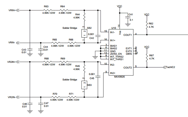
Image

This circuit is supposedly the same as the one you can find in the Microsquirt, MSPnP and also the MS3 Pro. With the difference right now being that i kept the resistors in-line with the signal from the MAX to the CPU, and no caps on the individual VR-in circuits for the simple reason that the board had no place for them. But as i said, i probably will alter it to its original design when i recieve my own board, which is through-hole design and the board is 99.5mm wide to be able to slide it into the case of a megasquirt to also have the possibility to run a proper VR conditioner in that department without any real SMD soldering troubles. On my part, SMD is not really a problem since i have a reflow oven, but i thought maybe some people would fin it appealing to build it themselves. In that case i can just reflow the MAX onto the board, and then people can install the rest by themselves. And it is also made with the philosophy of being easily altered to test different things with the MAX9926.
By noisymime
#7632
Love your updates, very helpful. 2 steps forward, 1 step backwards :?

I've pushed up a couple of changes just now that should both fix this issue and let it sync up a bit faster. These are a little more substantial and I haven't scoped them yet, so small chance of chaos :lol:
  • 1
  • 2
  • 3
  • 4
  • 5
  • 15

Had it running for a short period again. Same as […]

Ok, here is the first version of the adapter plate[…]

Ignition Angle doubled?

don't load your old tune in case it is corrupted[…]

Yes, totally wrong setting. Slight noise in TPS ca[…]

Still can't find what you're looking for?