Any strange behaviour, crashing issues etc, post them here! Problems compiling the firmware should go in the General support section rather than here
By hindsight
#43760
Hi there - I have a CORE4/ATmega based speeduino running for a Ducati engine (90 degree V-twin). I've been doing some bench testing, and one of the things that I have noticed is that the ignition advances significantly at high revs.

To test this, I'm using a 60-2 wheel, and have fixed angle mode enabled at 0 degrees, as well as the trigger angle set to 0 degrees, so the spark should coincide with the rise of tooth #0.

At lower revs (2000rpm in the below capture), it holds pretty solidly, and the ignition pulse goes low, shortly after tooth 0
Image

However - holding a simulated 7750 rpm, I see a lot of unintended advance:
Image

Investigating results over a wider rev range (using an automated test rig) I'm seeing a chart like this:
Image

Bearing in mind that for this, some additional error will be present by the method of measurement (which was an Arduino ATmega2560 reading the pulses, averaged over a sample of 250 data points per RPM).

Particularly, it seems to break down with occasional sync loss and very poor ignition timing at around about 7500rpm or higher.

I suspect this additional latency that is creeping in may be from the ATmega2560 itself. Is it struggling to keep up with higher RPM? If so, I'm guessing that the higher clock speed of a Teensy may well be the way forward...
User avatar
By PSIG
#43764
I have not seen issues with timing advance or retard at even very high rpm (much higher than yours), and by calculation it should not have issues, so I would say your assumption or concern that it is "struggling" to keep up with it is likely misplaced. I do not know the basis of your issue, but common factors for timing shift, drift or error can be various tune settings, reversed VR sensor polarity, gear or chain/belt-drive clearances, sensor lag, input circuit components (e.g., capacitor values), etc. I have no idea of any part of your setup, so I can't take a stab at likely gremlins.

David
By hindsight
#43765
Thanks for the reply David- bear in mind that this is a bench test, so it's not on an engine, but on an Arduino based test rig (which, itself is not guaranteed to be bug-free, but looks good in the oscilloscope).

That eliminates all physical engine components, leaving only:

* the CORE4 unit;
* crank signal generator;
* VR Conditioner;
* Ignition IGBTs;

To progress, I will eliminate both of the latter two by connecting directly to the CORE4, and I can certainly order another Arduino to test exactly the same on a "normal" Arduino, (rather than a CORE4, I mean). That would only leave the signal generator (the test rig), and I've already verified that with the 'scope.
PSIG wrote:I have not seen issues with timing advance or retard at even very high rpm (much higher than yours)
Good to hear - I'm particularly interested in the number of teeth on your wheel and how far in excess of what I'm observing you can go.

My current suspicion is that it's the combination of the high-tooth count and the high revs (which for me would generate a 15kHz interrupt at 7500rpm, which doesn't seem unreasonable for a 16MHz CPU to process), and I guess I can also verify that hypothesis by emulating a lower tooth count in the test rig (36-1 perhaps), and comparing the behaviour

I'll do some more testing later and post back.

Thanks,
Mike
By JHolland
#43766
Processor latency is only going to retard the ignition. If you are seeing advance then I would look at the VR interface, if you're not switching at the zero crossing but at a small positive offset then you will see advance. An offset can be caused by poor grounding/layout or by excessive current into the VR inputs.
By JHolland
#43767
hindsight wrote: Fri Jun 19, 2020 12:40 pm it's not on an engine, but on an Arduino based test rig (which, itself is not guaranteed to be bug-free, but looks good in the oscilloscope).
How are you generating the signal? if you use output compare properly then you shouldn't have an issue. If you use it Speeduino style as a timer interrupt then you may well run into issues.
By hindsight
#43769
JHolland wrote: Fri Jun 19, 2020 1:18 pmProcessor latency is only going to retard the ignition.
Apologies - typo on my part, you're absolutely right - ignition is retarded - I appreciate it's not apparent from the scope plot above, as that's a point in time that could be advanced or retarded, but when viewing it live, you can see the point that ignition goes low move from tooth zero rightwards (retarding).
JHolland wrote:How are you generating the signal? if you use output compare properly then you shouldn't have an issue.
Yes, exactly this - using output compare. The test rig is doing a few things (including measuring pulses and occassionally outputting aggregated data), so my test plan from here is:

1. Reduce the signal generating sketch to a bare minimum: eliminate all code except the crank signal and a tacho signal for verifying the output on the scope. Run at 6000,7000, and 8000 RPM - verify signal generator frequency on scope matches RPM, and observe retardation on scope.

2. Reduce the ECU hardware to bare minimum. Move the CORE4 from the current custom PCB into the breakout board, tie TPS to ground, IAT and CLT via resistors to ensure stability, and have one single connection from the signal generator to CKPS. Run at 6000,7000, and 8000 RPM - verify signal generator frequency on scope matches RPM, and observe retardation on scope.

If the same observation is visible at that point, then I suspect that it's definitely getting to the hardware, unless there is something else in there that I've missed. I'll also generate TS logs for both the tests along the way. I can also record a screen cap of TS & the oscilloscope.

Thanks,
Mike
By hindsight
#43773
It's the VR Conditioner that is at the root of this, and definately not anything to do with the Arduino.

Following the test plan above, I was able to reproduce the issue with a minimised signal generator, and validated the output on the scope. On step#2, I moved the core 4 into the breakout board, leaving only the RPM1 signal, and it ran perfectly at 8000rpm.

That showed that the problem had to be between the ECU CKPS pin and the CORE4. Removing the VR Conditioner module, and plugging the signal generator directly into the VR socket bypassed the issue.

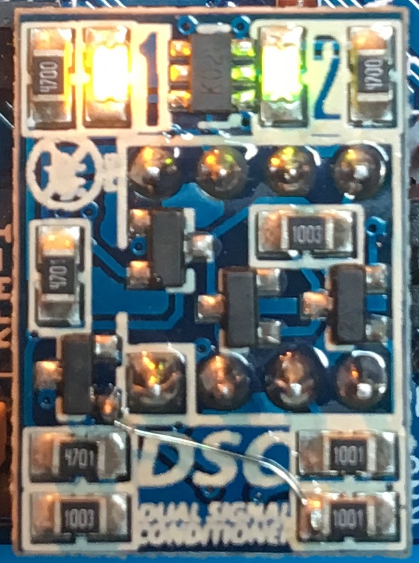
I'm certainly glad to have found this "on the bench" - much easier to diagnose that way. It's one of these that I have...
Image

Now - the question is.. I was passing a 5v square wave into it, on the expectation that it would trigger just the very same way as if the sine wave from the pickup, and that certainly seems to be the case up to about 7500rpm. Is there a flaw in my approach here?

Am I exceeding the capabilities of this particular VR Conditioner module?, or does it perhaps have a fault? Would I be better with a max9926 based unit?


For interest, I've posted a vid of the failure condition here.. on the scope, the purple trace is a tacho output from the signal generator with a period of one crank revolution, green is the (simulated) CKPS, and blue is IGN1. The test cycle starts at 6000rpm, runs for 15 seconds then moves to 7000rpm, and onto 8000rpm where you can see that the IGN1 timing starts to drift badly, and sync losses are starting to be logged in TS.

https://youtu.be/ELoxN8BbZ1s
User avatar
By turboedge
#43775
Hello,

This difference is probably due to the differing signal pull-ups on the board and on the DSC and how they react with the input filter capacitor. I think David mentioned this possibility. Changing the input filter to a lower capacitance is often recommended for hi-frequency trigger signals.

Weaver
User avatar
By PSIG
#43779
@hindsight — did you test signal in and out of the module no-load? I bench-test single modules provided from each dealer production batch to over 10,000 rpm on 60-2 simulated (10kHz) AC signal. I have also run 36-1 on a stock Ford VR setup machine-mount without issue to 13,400 RPM (ca. 8040 Hz), though the DSC circuit was tuned to 8000+. 9700 on running 60-2 project reports, though component tuning may have been needed.

If the bare DSC is defective or beyond tuned range it should show the drifting latency on a bench test, else it is likely an interaction with components or loads I have not tested. I have not tested DSC on a Core4. @Jama may have or be willing to.

Thank you. Ill try as soon as I can. These setti[…]

BMW E23 M30B28

cps.PNG With the crank at TDC, rotation is clo[…]

Had it running for a short period again. Same as […]

Ok, here is the first version of the adapter plate[…]

Still can't find what you're looking for?