Any questions you have before you begin buying, building and installing.
#66027
I have an old Lucas distributor as fitted to many 4 cylinder Ford cvh engined cars from mid 80's to mid 90's. I would like to run full sequential on engine. Crank pulley will have 36-1 trigger wheel with Hall sensor so I just need to get a phase signal from distributor to run FS.
The distributor is the basic electronic type i.e. still uses mechanical and vacuum advance but replaces contact breaker with electronic switch (described in workshop manual as Hall effect distributor).
The vac and mechical advance are easy to lock off but I am unsure best way to modify to get a square wave 5v phase signal.
AFAIK the sensor sends small pulses via 2 pin connector to amplifier module mounted on side of distributor. The module has a 3 pin connector to loom - power in, ground and signal (coil-ve). So presume the output is a 12v on off square wave? If so could this be simply changed to 5v signal to feed Speedy using voltage divider or similar?
The trigger wheel has 4 vanes and my first thought was just remove 3 of them so only one pulse per cam rev. But would that work - stator has 4 legs (magnets) - so does it rely on all 4 mag fields being cut to generate a large enough signal to passs to amplifier module?
I cannot scope anything at moment as car is in bits - just trying to forward plan for reassembly ;)

John
Attachments
IMG_20231128_185016764.jpg
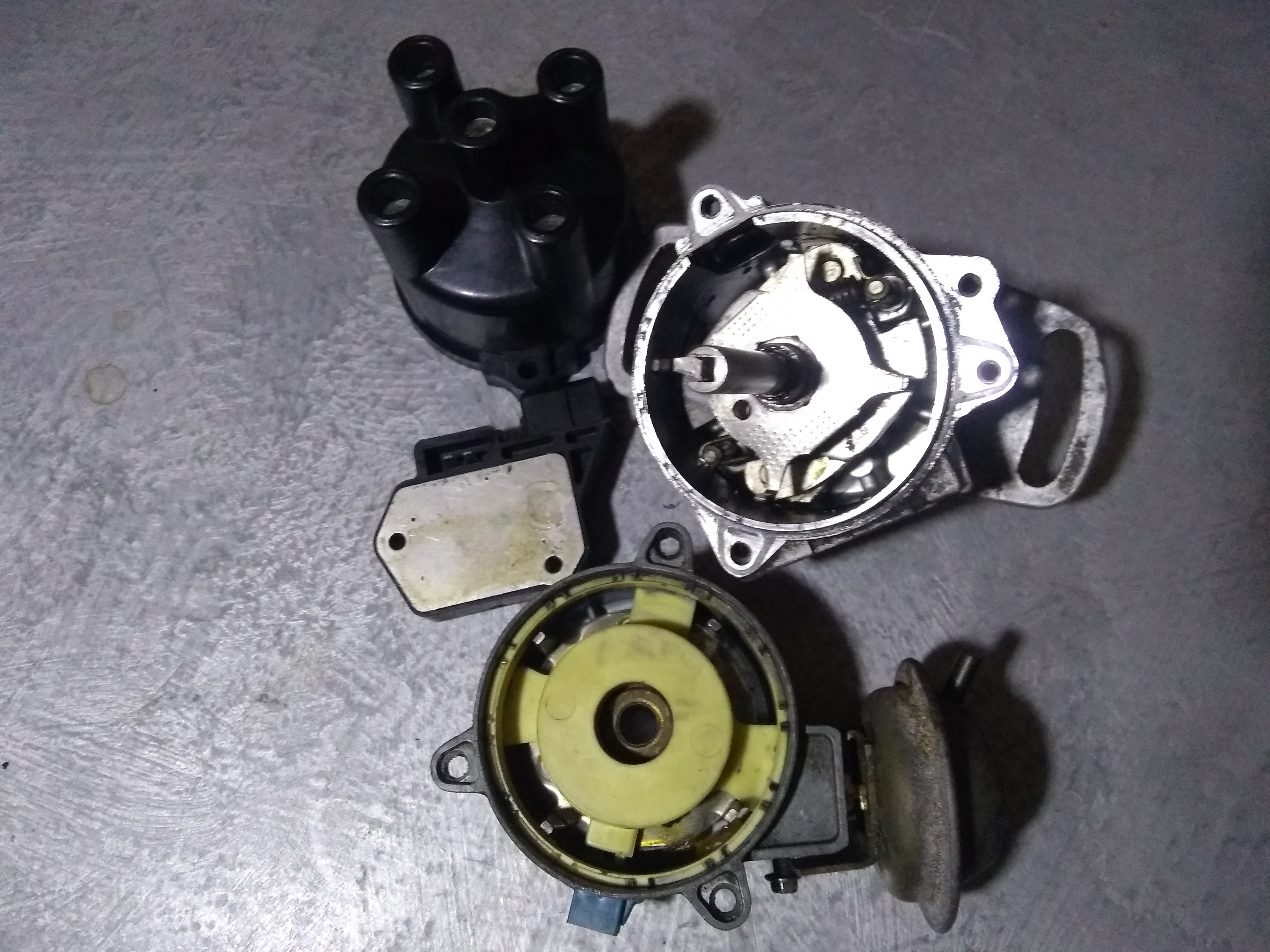
IMG_20231128_185016764.jpg (3.41 MiB) Viewed 1145 times
#66036
If removing trigger wheel vanes is ok can someone explain how this Hall effect sensor is working. The stator has 4 equally spaced pegs/magnets and the trigger wheel 4 equally spaced vanes. If removing 3 trigger vanes works that seems to suggest a pulse is only generated when remaining vane passes a specific stator leg.
#66041
I would power it up and 'scope it for signal character before cutting. Bench testing is fairly simple and can give you at least some of the info you need to know.

Stuff of that era is probably 12V powered, but unless you can verify that with a factory wiring diagram, I'd start with 5V just in-case. If it connected to coil(-), the output should be float/ground, but again that can be verified in testing so you know how to set it up.

Additional testing of the pickup (2-wire) signal will also tell you if that signal is VR or usable. I agree, chances are all 4 poles signal simultaneously for signal strength (similar to others again of that era), making a 3-legger not functional, but ... ;)
#66047
The "normal " distributors on the cvh in the UK that had the module hung on the side were a VR pickup not hall effect.
There were hall effect versions , but the one you should look for was what they fitted to the last of the mechanical injected xr3i and also the rs turbo escorts. These have a hall effect pickup and are fixed( I mean no centrifugal or vacuum advance )

This is the sort I mean
https://www.ebay.co.uk/itm/256307045388 ... media=COPY

There were MK2 and 3 fiesta (on carbs) also fitted with these. You can tell as they had a separate ECU not the side hung module.

If you want to use your existing dizzy you will need a vr conditioner of some kind. Be warned the signal is rather weak.
#66052
@PSIG. I quickly checked signal from pickup with meter and it looks like small ac and all legs combine together. So the only way this setup could generate a single pulse per cam rev would be to chop stator down to single post and trigger wheel down to one vane. Unlikely to work I think.

@dasq. Thanks for heads up on true cvh Hall effect distributor models - I suspected the unit I showed was VR rather than HE. I just checked my box of cvh distributors in garage and they are all the VR type ;-(

I really do not want to use VR conitioning in my Speedy installation so am thinking a better approach maybe to modify one of these distributors to HE by fitting an OE HE sensor operated by a trigger wheel or other ferrous target mounted on plate which carries centripetal advance weights. I suspect the vanes on standard trigger wheel may not be big enough but easy enough to use something else. @dasq you are clearly familiar with these distributors - have you been down the mod route?

John
#66054
Notarobot I have run cvh engines in various setups since the 80s.
I bought one of those hall dizzys many years ago when I was converting my quantum saloon to speeduino . I planned on using it just like you but with a later wasted coil pack , using the trigger as my cam reference.
I have attached some more pictures of the actual dizzy I have to assist you.
I am likely not using it now and it may be for sale in spring.

If you are going to strip and mod your existing distributor, consider fitting a small multi tooth trigger wheel such as 24-1 or better to save having a wheel on the crank.
Attachments
PXL_20231129_172637702.jpg
PXL_20231129_172637702.jpg (2.56 MiB) Viewed 1006 times
PXL_20231129_172708355.jpg
PXL_20231129_172708355.jpg (2.39 MiB) Viewed 1013 times
#66073
Thanks for the nice clear cvh Hall dizzy photos dasq.
Re 24-1 ... trigger wheel on distributor suggestion - the max diameter wheel that would fit inside the cvh distributor body is about 53/54mm and would be considerbaly less if HE sensor were mounted inside as well. Would trigger wheels of this size/pattern work ok? I assume have to be less accurate than crank wheel for crank angle.

As I have quite a few VR type distributors I can afford to sacrifice some for mods/bench testing. It would be nice to use an OEM HE sensor (for ease of replacement etc.) but so far they all look too big to mount easily. IC type HE sensors (e.g. Allegro) look like they should work with some sort of suitable mounting - their datasheet however uses a ref target wheel of 120mm diameter hence my question above about wheel size. I guess bench testing is only way to know for sure.

One other idea for phase detection - a lot of cvh engines have mechnical fuel pump operated by pushrod on lobe on camshaft. I have blanked off the mechanical fuel pump but did wonder if a modified pushrod running thru blanking plate could be used to trigger an HE sensor. A bit Wallace & Grommit I know :)
#66077
You can run very small ( 50ish mm od) trigger wheels, in fact quite a few do inside OEM dizzys.
But don't forget you only need the dog drive with the shaft support part of the dizzy. Cut the whole body away then you can have a bigger wheel . Obviously this is only an option if you are going coil pack and not using the dizzy to distribute sparks to plugs.

The important part about matching pickup to trigger wheel is the size of the tooth face not the od.

Not too sure about the fuel pump pin idea.

Some ideas attached
Attachments
Screenshot_20231130-173840.png
Screenshot_20231130-173840.png (947.95 KiB) Viewed 929 times
Screenshot_20231130-174415.png
Screenshot_20231130-174415.png (1.55 MiB) Viewed 929 times

I've managed to dig up a few obscure wiring diag[…]

Niiiice... 8-) Looking forward to your updates![…]

I'd be surprised if its not a 32-bit processor on[…]

I search for the datasheet of the IC and the on[…]

Still can't find what you're looking for?