- Wed Mar 20, 2024 6:38 pm
#67569
Hi,
TLDR; wanted to do a FI project, got a Honda J30 running with speeduino
Little bit longer version:
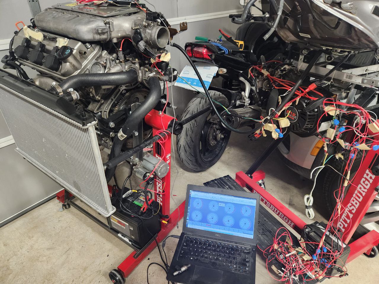
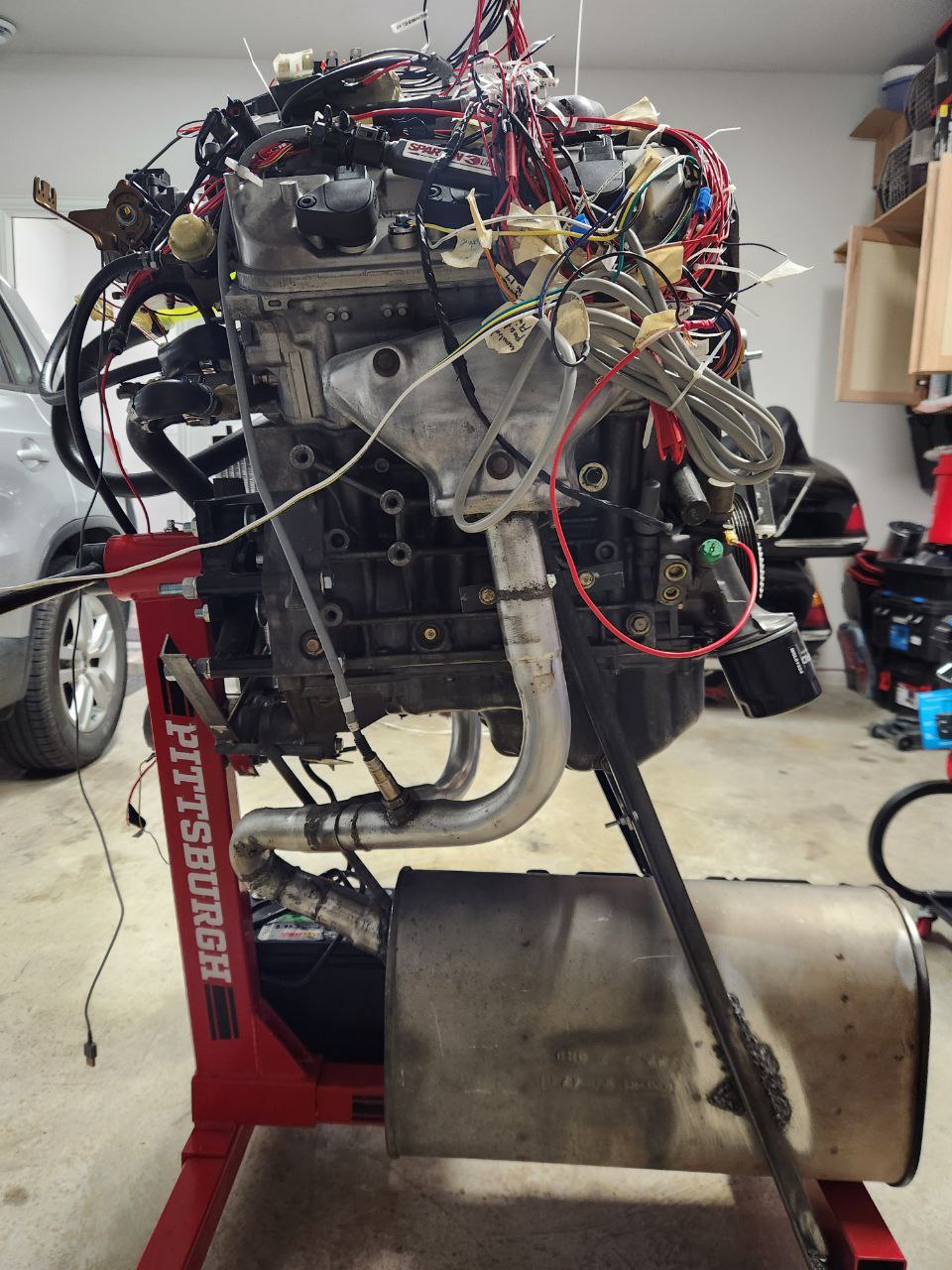
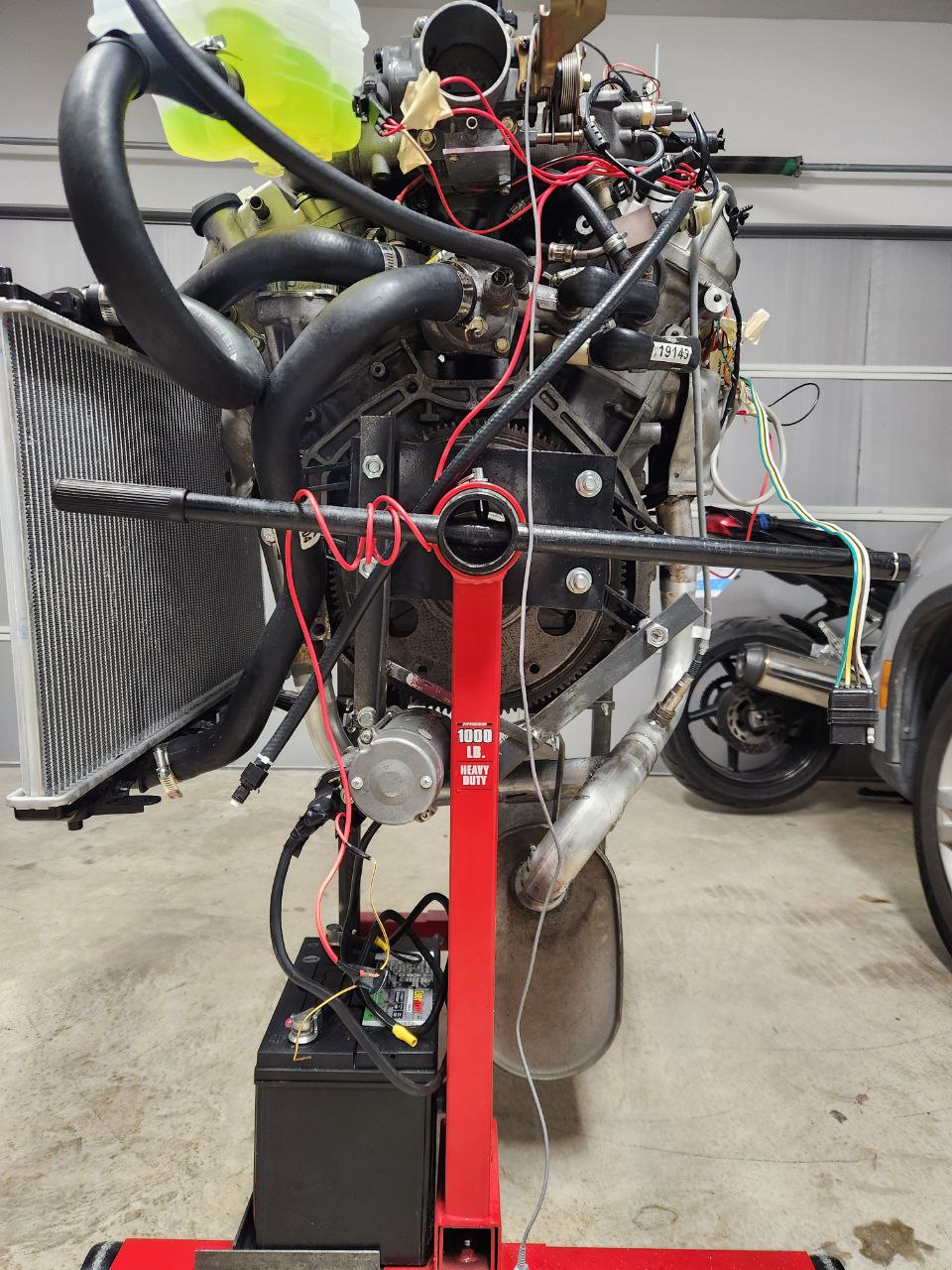
Here is the J30 on it's stand, the previous version of the project, a 212cc engine meant for lawn mowers and go karts (take the gold.. (Mario voice, totally not the the one from Mario Kart... All Nintendo references will be omitted from the final post)).
Here is the project file for the J30 with the settings used to start right now
https://raw.githubusercontent.com/alain ... ndaJ30.msq
And Here is the Predator one.. (search for some clever joke including chwairejlaieneger and the predator movie)
https://raw.githubusercontent.com/alain ... r212cc.msq
Lesser longer but no so smaller version... long long time ago in a far away land... a geek with a GS500 tough to himself... how difficult could it be to do a FI system, at that time I did the very dumb mistake of trying to do the whole thing as shields over the arduino... which was an interesting project.. but got the bike to run just for brief moments...
Last december I was like... another computer?... (sees from the corner of your eye the pile of thinkpads...) nahhh... and then I remember the itch with the FI, I did some research and bought the parts to build an speeduino, the 0.3 version with the surface mount components.... (they are like very small cars and worms running in the land of cooper traces... you gave them a mortgage on a through hole of the board and now they have to work forever....).
I initially thought of buying the J30 but notice Harbor Freight... (where the best tools are sold.... this message is brought to you by your inner mechanic... what does he use when he need something... Haaaaaaaarrrrrbor freigh... (read with pirate accent)) had the predator 212cc engine on sale for 99$ bucks https://www.harborfreight.com/65-hp-212 ... 69730.html , so I decided to try to get the thing running first on that engine and then if everything is good and the itch is not gone... buy the J30.
Eventually got the Harbor Freight engine running, used a CB500 throttle body and a CB500 fuel tank and fuel pump for the setup.
And then because I'm a very decisive person... right? I spent days thinking about it and then impulsively went to buy a Diet coke... nothing like diet coke for the hot winter right? well.. the dispenser was by pure luck on this place where they sell JDM engines... so
Note to whoever tries to replicate the adventure.. buy a engine crane (like for example the one on sexy red from HF (wink, sexy wink))... if you don't you will basically do some acrobatics, bolt the engine to an engine stand and then with the help of not one, not two, not three... but 2 jacks... not the one from the movie... got it down from the costco table where the j30 was waiting for the moment when the flimsy table broke and fall to the ground...
Now with the engine on the ground bla bla bla will complete the post later
Need to talk about
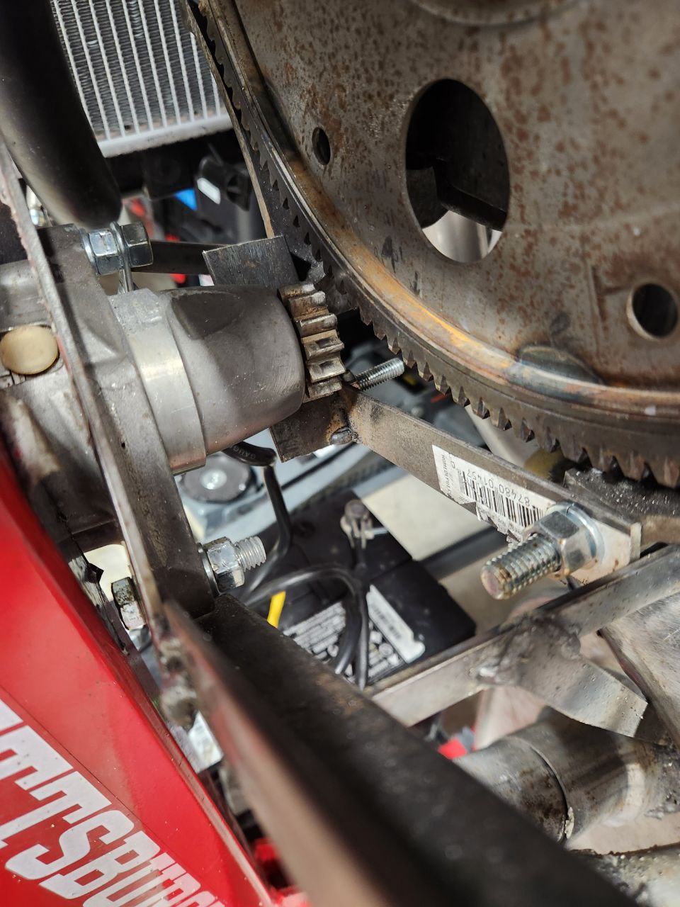
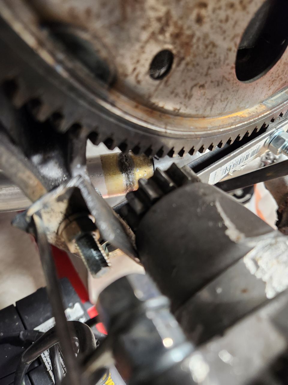
- Starter setup
- Use only the correct tools... the most amazing tools... the highest quality...
- 3d print pickup wheel and optic sensor for the predator engine
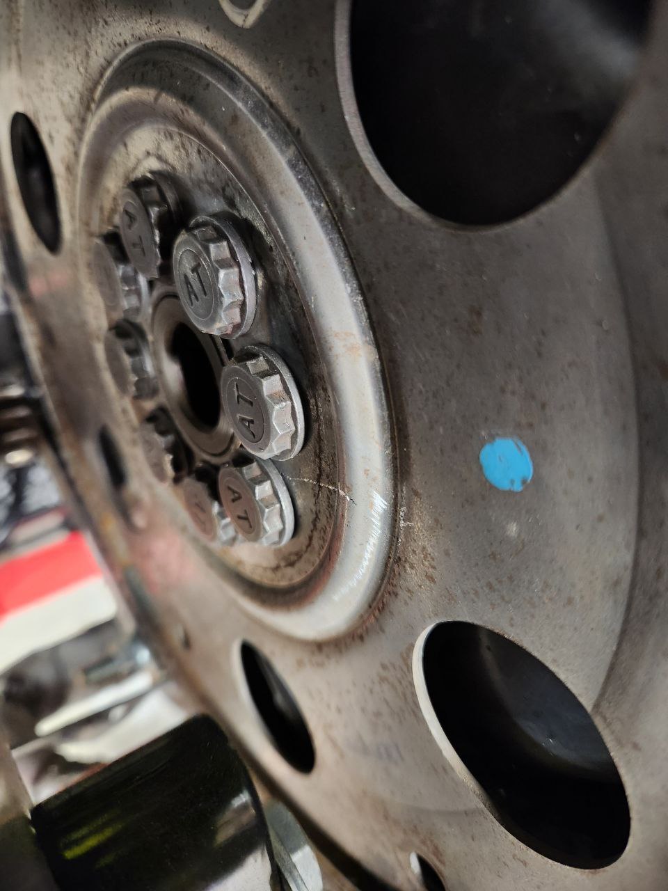
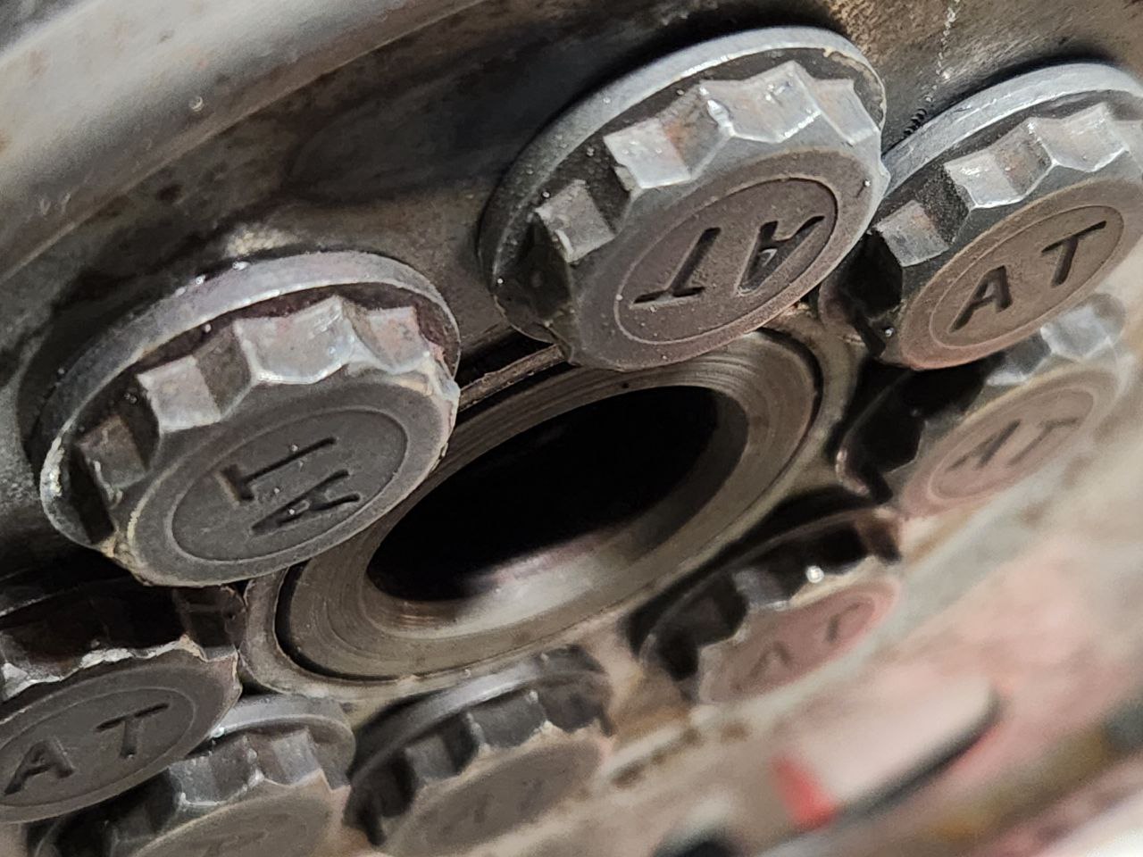
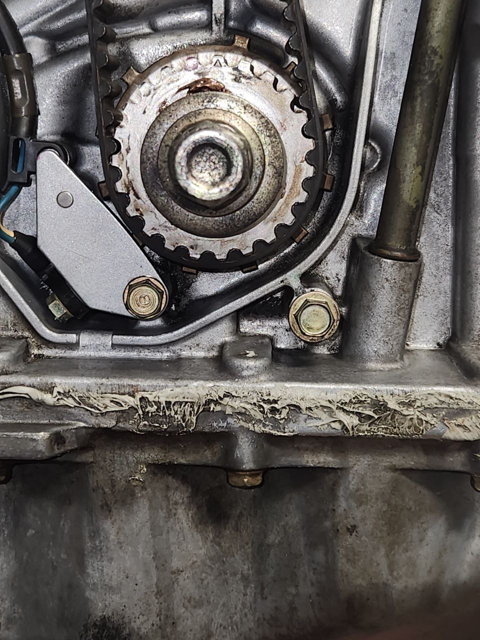
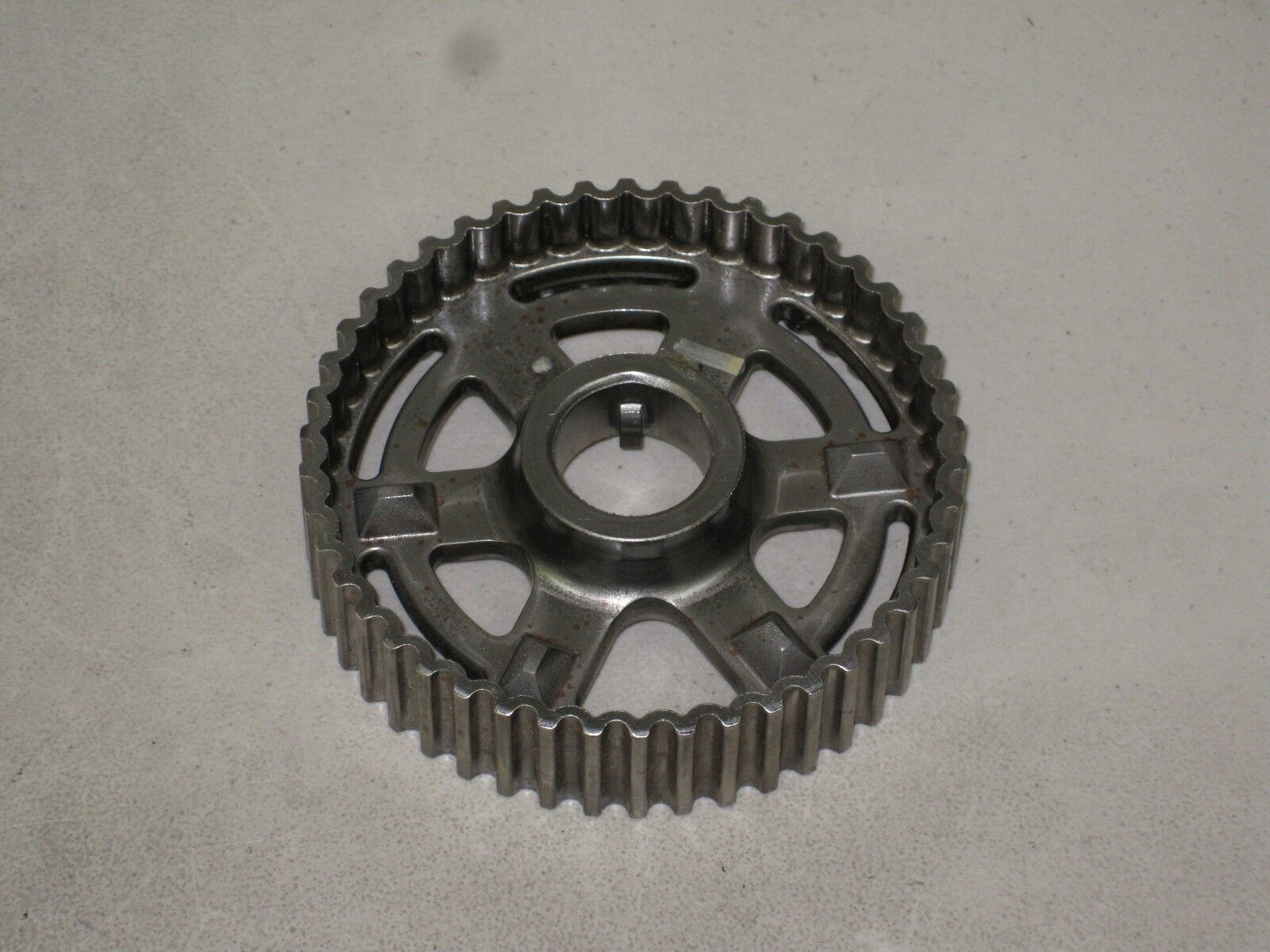
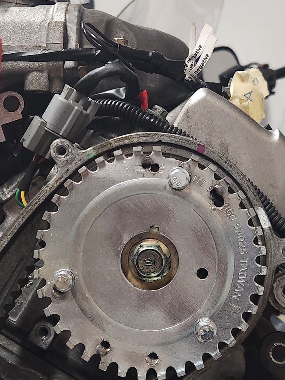
- 3d print 36-1 on crank pulley pickup wheel, modified cam gear with 36-1 wheel to use magnetic sensor, modifying the existing 12 thing already used by honda.... please do not use the dremel to have a 12-1 pickup wheel... that could work
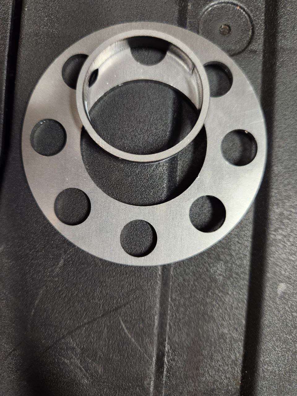
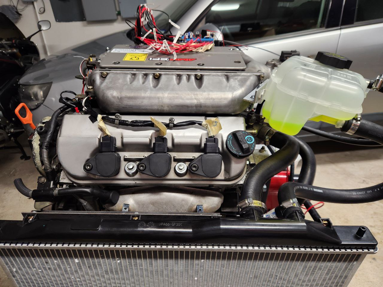
- use only genuine honda parts... like the honda camry flywheel... or the Toyot.... I mean HondOta camry starter.. or the I'm pretty sure Honda CHR radiator... or the honda 4runner fuel injectors because the ones that came with the engine were toasted
- I'm planning to tune the engine to something like 3k horsepower... I mean it has 3 stickers on the top... this is serious (not so serious to have a monster and a VR46 sticker yet... that's like top feed drag level...)
TLDR; wanted to do a FI project, got a Honda J30 running with speeduino
Little bit longer version:
Here is the J30 on it's stand, the previous version of the project, a 212cc engine meant for lawn mowers and go karts (take the gold.. (Mario voice, totally not the the one from Mario Kart... All Nintendo references will be omitted from the final post)).
Here is the project file for the J30 with the settings used to start right now
https://raw.githubusercontent.com/alain ... ndaJ30.msq
And Here is the Predator one.. (search for some clever joke including chwairejlaieneger and the predator movie)
https://raw.githubusercontent.com/alain ... r212cc.msq
Lesser longer but no so smaller version... long long time ago in a far away land... a geek with a GS500 tough to himself... how difficult could it be to do a FI system, at that time I did the very dumb mistake of trying to do the whole thing as shields over the arduino... which was an interesting project.. but got the bike to run just for brief moments...
Last december I was like... another computer?... (sees from the corner of your eye the pile of thinkpads...) nahhh... and then I remember the itch with the FI, I did some research and bought the parts to build an speeduino, the 0.3 version with the surface mount components.... (they are like very small cars and worms running in the land of cooper traces... you gave them a mortgage on a through hole of the board and now they have to work forever....).
I initially thought of buying the J30 but notice Harbor Freight... (where the best tools are sold.... this message is brought to you by your inner mechanic... what does he use when he need something... Haaaaaaaarrrrrbor freigh... (read with pirate accent)) had the predator 212cc engine on sale for 99$ bucks https://www.harborfreight.com/65-hp-212 ... 69730.html , so I decided to try to get the thing running first on that engine and then if everything is good and the itch is not gone... buy the J30.
Eventually got the Harbor Freight engine running, used a CB500 throttle body and a CB500 fuel tank and fuel pump for the setup.
And then because I'm a very decisive person... right? I spent days thinking about it and then impulsively went to buy a Diet coke... nothing like diet coke for the hot winter right? well.. the dispenser was by pure luck on this place where they sell JDM engines... so
Note to whoever tries to replicate the adventure.. buy a engine crane (like for example the one on sexy red from HF (wink, sexy wink))... if you don't you will basically do some acrobatics, bolt the engine to an engine stand and then with the help of not one, not two, not three... but 2 jacks... not the one from the movie... got it down from the costco table where the j30 was waiting for the moment when the flimsy table broke and fall to the ground...
Now with the engine on the ground bla bla bla will complete the post later
Need to talk about
- Starter setup
- Use only the correct tools... the most amazing tools... the highest quality...
- 3d print pickup wheel and optic sensor for the predator engine
- 3d print 36-1 on crank pulley pickup wheel, modified cam gear with 36-1 wheel to use magnetic sensor, modifying the existing 12 thing already used by honda.... please do not use the dremel to have a 12-1 pickup wheel... that could work
- use only genuine honda parts... like the honda camry flywheel... or the Toyot.... I mean HondOta camry starter.. or the I'm pretty sure Honda CHR radiator... or the honda 4runner fuel injectors because the ones that came with the engine were toasted
- I'm planning to tune the engine to something like 3k horsepower... I mean it has 3 stickers on the top... this is serious (not so serious to have a monster and a VR46 sticker yet... that's like top feed drag level...)
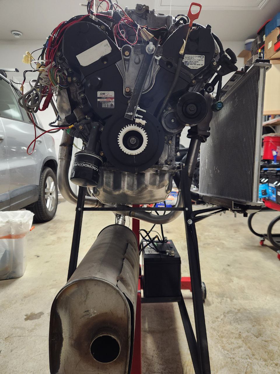
Honda J30 engine on engine stand...
Predator 212 engine on engine stand....
Number of kludges on J30: 15
Number of extremely bad practices used during the J30 project: 129
Predator 212 engine on engine stand....
Number of kludges on J30: 15
Number of extremely bad practices used during the J30 project: 129


 and use it as starter motor, or use the honda flywheel and starter.