Any questions you have before you begin buying, building and installing.
#35648
PSIG wrote: Sat Jun 15, 2019 4:04 am

EDIT - If you think they are backwards, and in order to to verify before rewiring; disassemble one connector and push the terminals forward (slide the connector housing down the wires a bit) to give enough slack to manually plug the wires in the other order, e.g., upside down. Check carefully that no terminals are touching, or slip an insulator sheet between them. Test for spark on that coil. Success = begin rewiring. No joy = cuss at me a few times and research LS3 wiring. :lol:

David
No problem, I have had fun looking at this, maybe I am looking in the wrong places, but it has been entertaining trying to find any information about the 2 different pin outs for these coils and which goes to which....
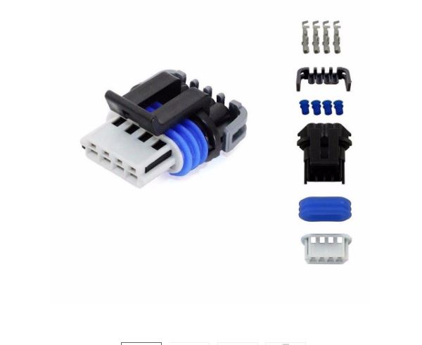
I have not opened up many connectors before, but it would be simple if I knew how to unlock the terminals and pull them out. (haven't picked up a set of terminal pins yet) in looking at the parts for the terminal. it looks like the white plastic piece needs to be removed first, just not finding the right place to depress to slide it off.... then depress the tang on the spade to slide them out
Attachments
COIL CONNECTOR.JPG
COIL CONNECTOR.JPG (24.19 KiB) Viewed 8070 times
#35657
Oops, those are the 150-series 'rear-load' (there are also 'pull-to-seat' or P2S in the same Metri-Pack series), so remove the rear retainer (where the wires come out) by popping off each end. Then you can press the single locking tab on each metal terminal inward to allow the terminal to slide out. Depending on the specific construction, the tab may be pushed inward at the little 'window' on the side where it engages (usually under the sealing ring), or from the front in the little slot provided (often called the top of the top-hat shape :roll:).

Check your tab after removal, and you will likely need to bend the tab out again so it will lock on reinsertion. Don't over-bend or overwork the tab or it will break off. For tools, I most often use a large straight pin, hat pin or T-pin, though little flat and pin tools can be made or bought.

David

Metri-pack 150 series female:
Metri-pack_Fem_rear-load.jpg
Metri-pack_Fem_rear-load.jpg (41.82 KiB) Viewed 8063 times
#35662
thanks for the side picture, a simple push the wire into the plug, insert the pin, & pull back on the wire, and presto, the spade comes out. life is simple with the correct knowledge..
in checking all the coils AC DELCO # 12611424, this link has a spec sheet for them https://www.jegs.com/i/ACDelco/065/D510C/10002/-1
I could not find any continuity between any of the pins and the HV spark terminal. so I am assuming that they are all still good.
I am using a 35 amp 14VDC relay #871-1A-3-R1
https://www.mouser.com/ds/2/378/2009829 ... 0-3428.pdf
what amp of fuse should I be using, to feed the coil? is the 10 amp to small?
#35668
thought I would post a couple of pictures of how to I pulled out the pins and changed them around, not bad once things came together, now when cranking, the fuse is not blowing. one small step...
now onto the next steps...
Attachments
65 disamble connector.jpg
65 disamble connector.jpg (147.27 KiB) Viewed 8057 times
66 tabs on the back side of the connector.jpg
66 tabs on the back side of the connector.jpg (117.48 KiB) Viewed 8057 times
67 front tabs on the blades .jpg
67 front tabs on the blades .jpg (160.71 KiB) Viewed 8057 times
68 wired correctly .jpg
68 wired correctly .jpg (254.86 KiB) Viewed 8057 times
#35696
looking at my idle setting, that are set up in tunerstudio. there are a couple of items that I am having fun with. first, for the life of me, I can't locate the screen where the high idle is set. before I realized, that I would not be using a spark plug J-type thermocouple , and went with a thermistor, I put in the number of 419, for the temp. it would be nice to change it to a lower number, but so far I am having a fun time finding that correct screen to make the change...to in the area of 150 degrees, where the themistor is located in the valve train...

the next question is about the GM stepper motor settings. in my set up, I am using a 1998 Saturn LS2 throttle body, I am assuming that I would be using the open loop settings, and not the closed loop....
if so I am thinking that I entered in the correct stepper idle values . I have been looking at the wiki page and searching the forums, just want to verify that I have it somewhat in the ball park.
https://speeduino.com/wiki/index.php/Idle
Attachments
idle settings questions.JPG
idle settings questions.JPG (93.19 KiB) Viewed 8041 times
#35698
when I found out that the J type spark plug thermocouple would be a little more entertaining at the moment to use. I purchased the thermocouple below, assembled & installed one in the cylinder head on my motor. where from what I am seeing, with an air cooled motor, I am needing a temp sensor, to let the speeduino know when to come down off the high idle.


https://www.mouser.com/datasheet/2/18/A ... 157013.pdf
Attachments
21 ready for assembly.jpg
21 ready for assembly.jpg (271.13 KiB) Viewed 8039 times
21 installed in cylinder head.jpg
21 installed in cylinder head.jpg (294.51 KiB) Viewed 8039 times
#35703
Barthoward54 wrote: Sun Jun 16, 2019 11:18 pmfirst, for the life of me, I can't locate the screen where the high idle is set.
That idle setting in your image is only for on/off idle control. Ignore it as it is grayed-out and inactive. The one you're after with stepper is Startup/Idle > Idle - Closed loop targets.
Barthoward54 wrote: Sun Jun 16, 2019 11:18 pmthe next question is about the GM stepper motor settings. in my set up, I am using a 1998 Saturn LS2 throttle body, I am assuming that I would be using the open loop settings, and not the closed loop....
Yes, always begin with Open Loop, to allow settings in steps and find where your IAC functions with your engine for a given rpm range and for step settings. Once tuned well, predictable and stable, then Closed Loop can be tuned much easier knowing how it responds and the range it should be active.
Barthoward54 wrote: Sun Jun 16, 2019 11:30 pmI purchased the thermocouple below, assembled & installed one in the cylinder head on my motor. where from what I am seeing, with an air cooled motor, I am needing a temp sensor, to let the speeduino know when to come down off the high idle.
https://www.mouser.com/datasheet/2/18/A ... 157013.pdf
Now that's a cool thermistor. -40 to 572°F! 8-) Anyway, for others tracking this, there are more useful references for use of that sensor under the "Other Related Documents" on this page. Another popular choice for CHT compatible with Speeduino include the little Bosch 0 280 130 012 or 022-906-041 as used on VW air-cooled engines, inexpensive, short 10x1mm straight threads (easy to tap) and easy to calibrate. Lots of options!

David
#35795
is it normal for the ground resistance to the to rise when the key is turned on and power applied to the board? I am getting a consistent reading when testing all the speeduino grounds. on pins 9, 10, 12, & 23. was able to post a video on the facebook page,
https://www.facebook.com/groups/1919187 ... _processed
but here are the pictures

also seeing if a datalog file will download, of some cranking with no spark. trying to see if I have things set up right, and just fried the coils, I am still getting a trigger signal out of the coil harness pin C, with using an LED diode.
Attachments
data log of a cranking with no spark?
(128.11 KiB) Downloaded 226 times
75 key turned on with ground.jpg
75 key turned on with ground.jpg (287.68 KiB) Viewed 7993 times
74 key turned off with ground.jpg
74 key turned off with ground.jpg (298.73 KiB) Viewed 7993 times
#35798
Interesting, I haven't actually tried that test, except to verify harness resistance through connections. Hmm. My first and totally random thoughts are that: it shouldn't vary, assuming your other dedicated Speeduino ground pins (except one for sensors) are appropriately grounded (multi-wire on star-ground) on chassis ground (engine block). Grounding resistance also increases with current, so your static results may change when operating. Otherwise, Speeduino does dump regulation into ground, but overall that shouldn't cause an issue with trigger signal ground return (I assume that's the pin you're on?). On the other hand, LS coils are typically and unofficially grounded with both signal and power ground to the engine block, as this tends to reduce noise, especially if not using noise capacitors. You may be onto the source of that, though it would be with other systems beyond Speeduino.

Are you using a noise capacitor between your harness coil V+ and power GND wires or block? That could affect your readings as it charges/discharges with meter or ECM power. Thinking out-loud. What's your base resistance for the bare loom vs on Speeduino, vs coil connected? Let me know if you find anything of interest in your search for clues.

David
#35800
[quote=PSIG post_id=35798 time=1560992062 user_id=149]


Are you using a noise capacitor between your harness coil V+ and power GND wires or block? That could affect your readings as it charges/discharges with meter or ECM power. Thinking out-loud. What's your base resistance for the bare loom vs on Speeduino, vs coil connected? Let me know if you find anything of interest in your search for clues.


no I am not using any noise capacitor,
checked for voltage drop, and it is all looking good, at least from everything that I have checked so far.
question, I know I am getting a crank signal out of the coil trigger connector, but with out an oscilloscope, what method is there to see what voltage is coming through the signal? I'm just wanting to verify that I haven't messed things up to bad.
I think I will be ordering some new coils tomorrow, from what I think I am seeing, everything coming from the board is checking out. but it is coming to a dead end once it hits the coils.
would there be a simpler set up than the LS coils?
thanks again for all the help.
  • 1
  • 2
  • 3
  • 4
  • 5
  • 7

nice first of all, i read all that crap months a[…]

I rewired a few grounds and tested the TPS and rel[…]

Thanks, car runs great now !!! Going to drift even[…]

sauver moteur v8

bonsoir je m appel jean marie et j habite en Franc[…]

Still can't find what you're looking for?