For anything not related to Speeduino, but still about car/bike/boat/engines etc
By Nitro
#31177
Hey guys. I'm trying some paralel projects and I thought it could be a good idea converting an single coil engine to multi coil engine. The objective is to eliminate the distributor ignition and use one coil per spark plug.
The engine is a 90's efi and I'm trying some efficiency experiments on it.
To make it work, I was thinking about using a arduino to "mimic" the dwell time of the ECU conected to it and to switch each coil by using a hall sensor. I'll use 4 of the same coil model to make sure it can handle the dwell time. But the problem I'm facing now is: How to code this?
Im not a master at ilustrating so I simplified some things :oops:
Thanks
Attachments
BobIndividuaisIlustrada.png
BobIndividuaisIlustrada.png (8.2 KiB) Viewed 8979 times
User avatar
By PSIG
#31183
Nitro wrote: Sat Jan 12, 2019 2:05 amThe objective is to eliminate the distributor ignition and use one coil per spark plug.
The engine is a 90's efi and I'm trying some efficiency experiments on it.
To understand and follow your logic plan for improving efficiency:
  • What is the basis of the efficiency improvement (how will it gain efficiency)?
  • Is the Hall sensor a different timing source from the one the original ECM uses?
  • Is the Hall sensor a cycle signal or include a cycle signal?
  • How is your plan different from a Speeduino sharing the original sensor or ECM ignition signal and adding a cycle signal, then firing the ignition piggyback-style?
I can assume some things or guess, but I want to understand your concepts.

David
By Nitro
#31204
The experiment is to prove if distributor ignition makes the spark weaker. A lot of people say it does and a lot say it doesnt. So I want to prove it by myself.
The hall sensor is a small circuit exclusively sending signal to the arduino. I placed magnets in a pulley in the crank shaft. It will guide the arduino when to change which coil it will drive when receive the negative signal from the ECU. The distributor will remains but only for the ECU hall sensor.
The arduino must drive the coil at the signal of the ECU. It must repeat the ECU signal on real time to make the same dwell.
I'm not using speeduino for now. I'm learning how it works before buy one. That project is not related from speeduino :oops:
User avatar
By PSIG
#31209
Nitro wrote: Sat Jan 12, 2019 8:21 pm The experiment is to prove if distributor ignition makes the spark weaker. A lot of people say it does and a lot say it doesnt. So I want to prove it by myself.
That's cool. 8-) Before trying to code this, there needs to be better hypothesis in order to get good results, and know how to structure the code. In other words, you need to know how to operate and measure for the correct answers (proof) to your hypothetical questions. Are you trying to prove that avoiding the cap and rotor gap is better? Or that shorter plug wires are better? Or that spark energy is better if the dwell does not have to be reduced at high-rpm? Or that most sequential systems are more accurate (thus better average engine power) due to crank angle triggering? And so on.

While following scientific method is the standard for moving toward good answers, a common fault is assuming one result is due to a certain cause, and missing the influence of other factors. In order to make a good test, you must at least know how you are going to measure results, and if that method will give you the information you need for proof. For example, if measuring if the spark energy on a path through a distributor makes it weaker than direct from the coil; this would require a means to measure the spark energy voltage, amperage and duration, or degree of spark ionization versus duration, etc. To attempt measuring by a variation of fractional engine power at a specific AFR and temperatures, while under specific RPM and load on any engine (most of which vary far more than that on any given day), will likely end in frustration for lack of proof. There are too many additional variables and factors that can influence the results.

This would point to greatly simplifying the experiment to a table with an ignition circuit (battery, Arduino, coil driver, coil, plug wire, spark plug), that also includes adding a coil HV wire, distributor cap and rotor for the direct comparison. The Arduino can simply fire the coil on-demand with a fixed and consistent dwell on the exact same coil and components for each test. The Arduino Blink sketch slightly modified for dwell duration could work for that, and you could have results today with no additional effort or bad info due to other environmental errors and factors. ;)
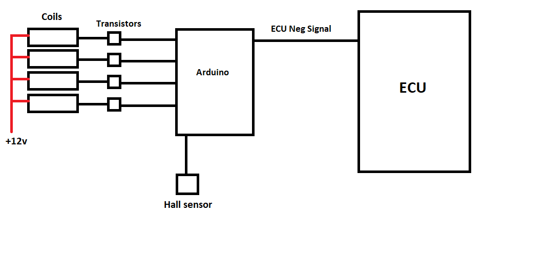
Nitro wrote: Sat Jan 12, 2019 8:21 pmThe hall sensor is a small circuit exclusively sending signal to the arduino. I placed magnets in a pulley in the crank shaft. It will guide the arduino when to change which coil it will drive when receive the negative signal from the ECU. The distributor will remains but only for the ECU hall sensor.
Without a cycle signal, the Arduino can not know whether to fire the coil sequentially for TDC #1 or TDC #4. You want sequential spark when the crank trigger only provides 360° information, while a 4-stroke cycle is across two crank rotations (720°). Cycle sensors are commonly called cam sensors due to their typical placement. Without the cycle signal, you would have to fire waste-spark, which will usually give the same results firing every TDC — depending on your specific hypothesis. ;) Give us the new hypothesis and means of measurement, and perhaps we can help you to outline a simpler experiment that will provide the proof you are after. I hope that helps!

David
By dazq
#31213
This sounds like the spark router project that megasquirt had to give them sequential in the early days?
Perhaps a search for info on that may help your design.
By Nitro
#31215
Guys. I'm not intending to go so scientifically on this :oops:
The only measure method I have is to compare how the engine parameters change from one system to another using VCDS lite. :(
And the plan isnt to make the arduino a ignition module. The plan is to make it a "coil switch". I think it needs to depends of the ECU to fire the coils correctly. Yeah, the arduino will drive the coils, but at the ECU call only.
I placed 2 magnets. At each 180 degrees the hall sensor sends a signal to the arduino.
It must work like:
ECU signal, Ignition coil 1 fires
*Crank rotates 180° and arduino hall sensor sends a signal*
ECU signal, Ignition coil 2 fires
*Crank rotates 180° and arduino hall sensor sends a signal*
ECU signal, Ignition coil 3 fires
*Crank rotates 180° and arduino hall sensor sends a signal*
ECU signal, Ignition coil 4 fires
*Crank rotates 180° and arduino hall sensor sends a signal* (this time to back from the start)

I tried some "if" with "count" codes but it didn't work so well in the simulations. :(
By dazq
#31224
I'm not surprised you are having issues!
In your scheme you mention , how does the Arduino differentiate between it being time for 1 and 3 on the first magnet or 2 and 4 on the second magnet.?
You need a No1 ONLY signal point to start the cycle.
By Nitro
#31227
It wont diferentiate. It will work with coincidence. When I place the coils in the right order with the engine on TDC, from this point, when I start the engine, the circuit/code will make coincide where a coil must fire. Since it is a fixed order(code and engine) with a fixed orientation (hall sensor) it will always coincide. Thats why I place the sensor and magnets in the crank.
The magnets are placed to pass in the sensor when the crank turn 90 degrees. The arduino will be ready to fire a coil before TDC. When the crank reaches TDC the ECU will signal the arduino to fire the coil. I think the code must use a if/else to work with the ECU signal, so the arduino will dwell the coils exaclty as the ECU does. The arduino will be used to follow that system and not to execute a sequence.
For the ignition sequence, example:
pin 1 drive the coil in the cylinder 1
pin 2 drive the coil in the cylinder 3
pin 3 drive the coil in the cylinder 4
pin 4 drive the coil in the cylinder 2
By LPG2CV
#31233
As psig and dazq have indicated, you have to have a signal from the cam (or dizzy) to enable your arduino to know which part of the cycle cylinder #1 is on. You can't get this information from the crank.

As you not need the rotor arm in the dizzy to distribute the spark, you could possibly modify the cap to accept another hall sensor (or optical) to read from a modified rotor arm. The rotor arm (or its replacement), would need to be ferrous (hall sensor) for the sensor to work.

Then, your code structure will look at IF you have signal from both sensors, THEN, you are on cylinder #1 and set your counter to 1, then as you were indicating, increment your counter until you get to 4, then reset to 1.

Also, a dizzy cap and rotor arm are relatively easy to source and replace back to OEM.

Consider Bosch 211 for your ignitors.

Good luck. Interesting project. :)
By JHolland
#31236
You can run one coil per plug in wasted spark without a cam sensor. The biggest difference is likely to occur if you use a higher energy coil - the problem with that is that you ECU may not be set up correctly in terms of rise time/dwell time so you could damage the coils. If you were to use the Speeduino to control the ignition then you would be able to adjust the dwell and experiment with modified timing. Otherwise there is no real problem with the concept, the early MX5 ECUs implement a similar scheme.

In my opinion the easiest way is to just leave out[…]

Cant seem to get it working. Uploded my 202402 ini[…]

nice first of all, i read all that crap months a[…]

I rewired a few grounds and tested the TPS and rel[…]

Still can't find what you're looking for?