Help with building your Speeduino, installing it, getting it to run etc.
By evo_lucian
#2653
Created this thread to document my progress and to hopefully help a couple person along the way. The car is a 1997 honda civic Ferio with a SOHC 1500cc engine with manual 5 speed transmission.

Image

Speeduino V.04 2 channel PCB with Sainsmart Arduino Mega

Image

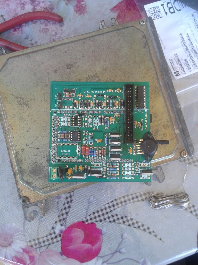
Set up will be run on basic Distributor Trigger option with Batch injector firing. Trigger set up will be 4 tooth trigger wheel and single coil, inside the stock honda distributor wired to a LM1815 VR conditioner.

Ok so my board is fully assembled and patch harness built and I have a couple questions,

On my car's stock harness injectors 1 & 4 are coupled and 2 & 3 are coupled together, I wired inj 1 & 4 to pin 1 and inj 2& 3 to pin 2 on the V0.4 IDC connector. Is this correct ?

I connected the fuel pump relay signal wire to pin 14 on the V0.4 IDC connector ( low current output 1), When I switch ignition on, the pump stays on no matter what i enter in as the Priming pulse in TunerStudio.

Now I have not attempted to start the car because I am still uncertain about the injector wiring and also I have not figured out the resistor and capacitor placement on the VR conditioner PCB RichCreations drew up. i guess I can always trace the circuit with a multimeter but my POS meter just cant seem to give me a break. Any help would be greatly appreciated.
Last edited by evo_lucian on Thu Oct 22, 2015 6:37 pm, edited 2 times in total.
By noisymime
#2658
Awesome work!

I have a horrible feeling that I've just noticed a problem on the v0.4 board that you might have been the first to pick up though :oops:
The labels on the board for Q3 and Q2 appear to be the wrong way round. Where you've put the 2nd MOSFET over in the corner is actually the injector 3 circuit, not injector 2. You'll need to move that mosfet over the the place labelled Q3.

Of somewhat more importance, you have a lot of those mosfets soldered in backwards. :o
Q1 looks OK, but the rest look like they're backwards. If you see the 3 little boxes on the board marking, those show you the side that the tab on the mosfet should go. This is almost certainly what is causing your fuel pump issue. Those particular mosfets are pretty tough, so though hopefully should be ok.
It doesn't have the spare outputs populated, but have a look at the injector drivers on this:
Image

Do you have a link to a pinout for your stock wiring harness? It looks approximately like the 64-pin Denso ECUs. I'm just curious really.
By evo_lucian
#2661
noisymime wrote:Awesome work!

I have a horrible feeling that I've just noticed a problem on the v0.4 board that you might have been the first to pick up though :oops:
The labels on the board for Q3 and Q2 appear to be the wrong way round. Where you've put the 2nd MOSFET over in the corner is actually the injector 3 circuit, not injector 2. You'll need to move that mosfet over the the place labelled Q3.

Of somewhat more importance, you have a lot of those mosfets soldered in backwards. :o
Q1 looks OK, but the rest look like they're backwards. If you see the 3 little boxes on the board marking, those show you the side that the tab on the mosfet should go. This is almost certainly what is causing your fuel pump issue. Those particular mosfets are pretty tough, so though hopefully should be ok.
It doesn't have the spare outputs populated, but have a look at the injector drivers on this:
Image

Do you have a link to a pinout for your stock wiring harness? It looks approximately like the 64-pin Denso ECUs. I'm just curious really.
Image

I will flip them around and see what happens. I was wondering what the 3 boxs were for lol.

the pinout for my ecu is here. 2nd one down (2 connector)
http://www.dodo-upgrades.nl/obd1swapd14a34.htm

Image

Image

I use these wiring diagrams as mine is sorta rare, only difference is that my injectors are batch
Last edited by evo_lucian on Thu Oct 22, 2015 7:59 pm, edited 1 time in total.
By evo_lucian
#2665
Old Grey wrote:Can you take a pic of under the board, I would like to see the processor.
Image

So I have no luck desoldering the MOSFETS so i broke them off at the base of their legs and will wire the fuel pump to ign on 12v then later this week I will use some breadboard wires and solder the mosfets remotely like like this . I HATE DESOLDERING !!!

Image
By Old Grey
#2668
Now I see the rows of IDE header pins suspending the processor under the V0.4 - sorry I'm just starting on researching it -

You usually de-solder it by heating up 2 pins and rocking it.
By evo_lucian
#2670
Old Grey wrote:Now I see the rows of IDE header pins suspending the processor under the V0.4 - sorry I'm just starting on researching it -

You usually de-solder it by heating up 2 pins and rocking it.
Desoldering a component with 2 pins is usually easy. you use the soldering iron to heat it up then pull the component out when the solder has melted. Desoldering components with 3 legs like MOSFET's is a bit trickier since the soldering iron cant reach all 3 legs to least them up. Hopefully some soldering wick will help out, until then i will justt leave the pump wired to IGN switched 12v.
By Old Grey
#2674
It's actually for 3 pin components.

You heat 2 pins and rock it sideways so those pins come up about 1mm - if you don't mind more bend in the fixed leg rock it more -. Then you heat the opposite 2 pins and rock it the other way and slowly work it out.

I usually heat the solder and quickly bang the side edge of the board on the table - board hits the table perpendicular -, and that knocks out most of the solder. It sometimes means you only have to rock it once or twice each side.
By evo_lucian
#2677
Old Grey wrote:It's actually for 3 pin components.

You heat 2 pins and rock it sideways so those pins come up about 1mm - if you don't mind more bend in the fixed leg rock it more -. Then you heat the opposite 2 pins and rock it the other way and slowly work it out.

I usually heat the solder and quickly bang the side edge of the board on the table - board hits the table perpendicular -, and that knocks out most of the solder. It sometimes means you only have to rock it once or twice each side.
Thanks for the tips man. I will try it out next time
  • 1
  • 2
  • 3
  • 4
  • 5
  • 24

I rewired a few grounds and tested the TPS and rel[…]

Thanks, car runs great now !!! Going to drift even[…]

sauver moteur v8

bonsoir je m appel jean marie et j habite en Franc[…]

Ignition Angle doubled?

I just erased the flash, went back to 2023-10, cre[…]

Still can't find what you're looking for?