

- Sun Nov 29, 2020 5:42 pm
#46770
Assuming from your comments that the IAC has not moved at all at any time; if you carefully place +5V from a board source onto the channel input (see below), the powered IAC should snap fully open or closed. No? Then the issue is somewhere between your +5V test input and your (working?) IAC. You could begin testing from the board-out, or from the valve-in, such as applying direct +12V and GND to the IAC pins in order to verify the valve functions as-expected. Move to the wiring and connections, etc. If you know (not assume) the hardware works all the way to the processor, then you know it is a processor/code/settings issue, or else you already found your problem in the testing.
The issue we have is not knowing if you have tested anything or changed anything, or even made any simple mistakes; e.g., selecting the wrong board in TS Engine Constants. Without feedback or verification from you, we have no idea where faults may lie. However, it is unlikely that the default pin settings will be incorrect, as verified by many other users. Can you help us help you?
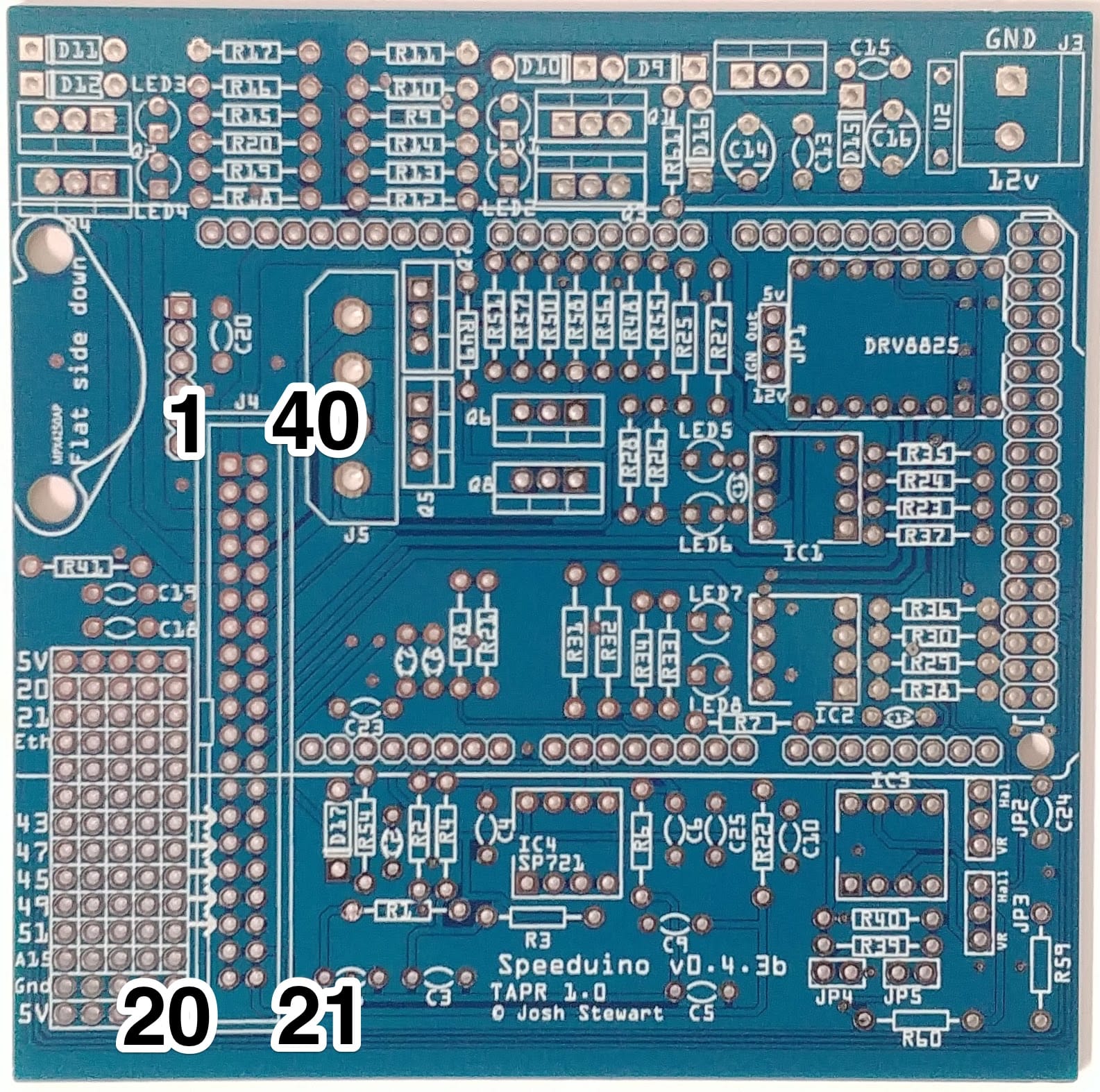
Verify this is your board type before testing:
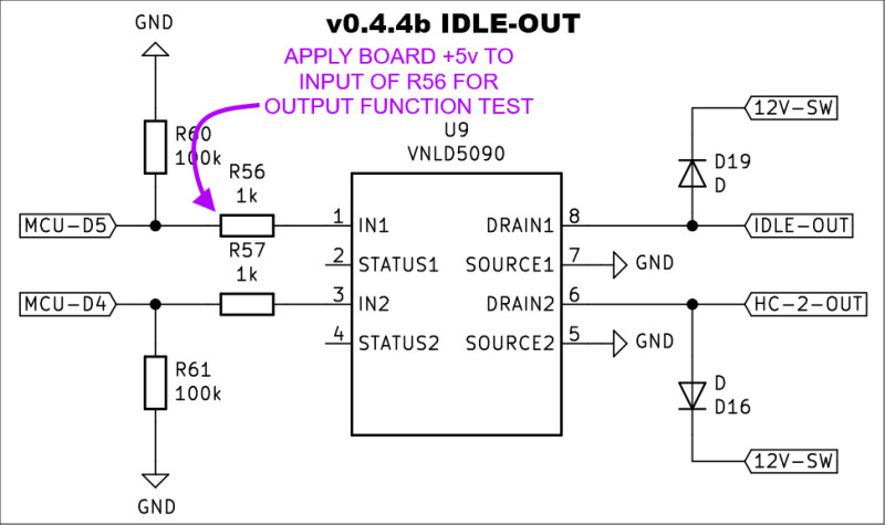 Spdno_v0.4.4b_Idle-Out.jpg (68.58 KiB) Viewed 3948 times
LAV1000 wrote: ↑Sun Nov 29, 2020 9:12 am What happens if you apply 5Vdc to the Arduino 5 pin ?Hugo, what @LAV1000 is suggesting is simply a test of the IDLE_OUT output. It is a different approach to my previous testing suggestions, which tests everything outboard of the processor for proper function. This approach separates the processor operation from the hardware operation, focusing your attention on where the issue(s) are.
Assuming from your comments that the IAC has not moved at all at any time; if you carefully place +5V from a board source onto the channel input (see below), the powered IAC should snap fully open or closed. No? Then the issue is somewhere between your +5V test input and your (working?) IAC. You could begin testing from the board-out, or from the valve-in, such as applying direct +12V and GND to the IAC pins in order to verify the valve functions as-expected. Move to the wiring and connections, etc. If you know (not assume) the hardware works all the way to the processor, then you know it is a processor/code/settings issue, or else you already found your problem in the testing.
The issue we have is not knowing if you have tested anything or changed anything, or even made any simple mistakes; e.g., selecting the wrong board in TS Engine Constants. Without feedback or verification from you, we have no idea where faults may lie. However, it is unlikely that the default pin settings will be incorrect, as verified by many other users. Can you help us help you?
Verify this is your board type before testing:
-= If it was easy, everyone would do it =-
 from the official page:

 - By pazi88