

- Mon Jan 25, 2021 8:11 am
#47810
This seems to be constant topic of trouble, so hoping that this post would clear up things related to VR-polarities and rising/falling edge trigger setting.
But as for start there is two main types of crank/cam sensors used in engines. VR and hall. There is others too, but lets not go to that rabbit hole now. VR-stands for Variable Reluctance and in practice it creates analog sine wave signal in which the frequency and amplitude varies depending on the engine rotation speed. You can read more from wikipedia: https://en.wikipedia.org/wiki/Variable_ ... nce_sensor
In the sine wave VR-signal, the zero-crossings mark the center of the tooth's and center of the pits between tooth's. And the depending on the VR-polarity, the signal can be going towards positive side at the center of the tooth or towards negative side. This is good picture showing that:
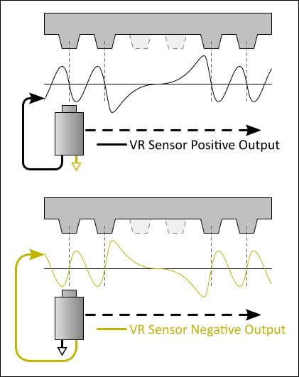
This analog sine wave signal isn't something that the Arduino mega in Speeduino can directly read. We need to condition the signal to 5v square wave and for that we use VR-conditioner. In this write up I use max9926 VR-conditioner, because I know it best. Caveats regarding to others can commented below. Maxx9926 has inverting open collector output that triggers at zero crossing. It means that in normal state, the output is floating, so basically behaves as wire connected to nothing. When the input sees the VR-signal going from zero to positive direction, it inverts the signal and grounds the output. So it's basically same as wire connected to ground. When the VR-signal goes back down from positive side and crosses the zero voltage line, the output again goes floating. This alone isn't doing much, but once we add pull-up resistors to the outputs, the resistors "pulls" the output voltage to 5v when it's in the floating state.

These pull-up resistors are generally included in the vr-conditioner boards, so you don't need to care about that. The main thing is that with those resistors, we get inverted 5v square wave signal out of the max9926 VR-conditioner. Now we input that square wave to speeduino processor and need to select the falling rising edge setting in TS. If we use the "correct" polarity for the VR-sensor, it means that the center of the tooth is at the zero crossing when VR-output signal is going towards positive side. Because the max9926 is inverting output, it means that the signal goes from 5v to 0v at the center of the tooth. So in TS we need to select falling edge setting to make the speeduino trigger at the point when the signal "falls" from 5v to 0. On the other hand if the VR-polarity is reversed, the VR-signal to the conditioner is mirrored. And that means that we need to select the rising edge setting in TS, to make it trigger when the signal voltage "rises" from 0v to 5v. NOTE! DSC VR-signal conditioner is non-inverting, so it requires opposite trigger edge than max9926 compared to VR-polarity

This is how it looks on actual scope. NOTE: the VR-signal is accidentally reversed in this pic: https://pazi88.kuvat.fi/kuvat/Projektik ... 203646.jpg
Ok, then comes the question that how do I know to select rising or falling edge if I don't own a scope. Well for that you need registered TS version and go to "Diagnostics & High Speed Loggers" -tab. There in composite logger, you should see this kind of view, when you log while cranking/running the engine:

Those bars represent time between each trigger point. This is taken from 60-2 crank trigger and there should be one bar that is three times the length of the others marking the 2-missing tooth. But now we have two slightly longer ones. What happened? This means that the VR-polarity is wrong or the falling/rising setting is wrong. It's now triggering to the center of the pits between the teeth. To make this clear that why you are seeing those two longer bars, here on green is where the ecu is triggering:

If we reverse the VR-wires OR change between the rising/falling setting, we get this where there is one long bar for the 2-missing tooth and ecu can easily sync with the engine:

Okay, what's the deal with the claim that you should use falling edge trigger with this or that VR-condtioner or rising edge with other one. Well let me explain. In speeduino the signal from VR-conditioner doesn't go directly to the arduino mega input. There is filter capacitors in the line too:

These serve good purpose, and as name says, those are meant to filter out unwanted noise in the signal input. But in case of max9926 vr-conditioner, there is that pull-up resistor that was mentioned earlier. When pull-up is used, the capacitor is charged through that 1k resistor, but it's discharged by basically short to ground when max9926 output is active, so there is no resistor slowing down the discharge current. This causes that once the engine RPM gets higher with the high res triggers (like 60-2), the square wave isn't anymore square, but more like shark fin shaped on the rising side:

The mega input has specific thresholds for low and high input level. The rising slope in the signal can cause that the high threshold isn't reached immediately when the signal starts to raise but slightly later (see previous pic). And this can cause same timing drift what can be seen as retarded timing at higher RPM. Here is an example when the retard in ignition starts to be about half the tooth width (closer to 2 degrees in 60-2):

To prevent this from happening on higher resolution trigger wheels, it's recommended to use falling edge trigger instead of the rising edge. And if you see the wrong crank signal on the composite logger with falling edge tirgger, swap VR-polarity, instead of using rising edge.
Ok, then little about hall-type sensors. With those, you don't need to care about VR-polarity. You can select the rising or falling basically freely if your trigger wheel is traditionally shaped. The selection just affects that do you trigger at the start of the tooth or at the end of the tooth (hall sensors don't trigger at the center of the tooth as vr-sensors do). And you just need to match the trigger angle to which one you select. But there is also same thing with hall sensors as there is with max9926. Many hall sensors have also open collector output so you need to activate the pull-up on the speeduino board. And that makes the hall sensors prone to same timing drift problem as VR-sensors when using rising edge trigger. And wait! It gets worse! If you need to use the pull-up on the speeduino board, it means that the filter cap is now charged through the 1k pull-up resistor and also the 1k protection resistor. So it's actually charged through 2k resistor:

So that makes the rise time of the hall signal even slower. So slow indeed that with high resolution trigger wheels (like 60-2) you might see problems that the crank signal doesn't reach the high threshold on the processor input and you will have sync losses at higher RPM. In this case, you need to swap the crank trigger filter to smaller one.
But as for start there is two main types of crank/cam sensors used in engines. VR and hall. There is others too, but lets not go to that rabbit hole now. VR-stands for Variable Reluctance and in practice it creates analog sine wave signal in which the frequency and amplitude varies depending on the engine rotation speed. You can read more from wikipedia: https://en.wikipedia.org/wiki/Variable_ ... nce_sensor
In the sine wave VR-signal, the zero-crossings mark the center of the tooth's and center of the pits between tooth's. And the depending on the VR-polarity, the signal can be going towards positive side at the center of the tooth or towards negative side. This is good picture showing that:
This analog sine wave signal isn't something that the Arduino mega in Speeduino can directly read. We need to condition the signal to 5v square wave and for that we use VR-conditioner. In this write up I use max9926 VR-conditioner, because I know it best. Caveats regarding to others can commented below. Maxx9926 has inverting open collector output that triggers at zero crossing. It means that in normal state, the output is floating, so basically behaves as wire connected to nothing. When the input sees the VR-signal going from zero to positive direction, it inverts the signal and grounds the output. So it's basically same as wire connected to ground. When the VR-signal goes back down from positive side and crosses the zero voltage line, the output again goes floating. This alone isn't doing much, but once we add pull-up resistors to the outputs, the resistors "pulls" the output voltage to 5v when it's in the floating state.
These pull-up resistors are generally included in the vr-conditioner boards, so you don't need to care about that. The main thing is that with those resistors, we get inverted 5v square wave signal out of the max9926 VR-conditioner. Now we input that square wave to speeduino processor and need to select the falling rising edge setting in TS. If we use the "correct" polarity for the VR-sensor, it means that the center of the tooth is at the zero crossing when VR-output signal is going towards positive side. Because the max9926 is inverting output, it means that the signal goes from 5v to 0v at the center of the tooth. So in TS we need to select falling edge setting to make the speeduino trigger at the point when the signal "falls" from 5v to 0. On the other hand if the VR-polarity is reversed, the VR-signal to the conditioner is mirrored. And that means that we need to select the rising edge setting in TS, to make it trigger when the signal voltage "rises" from 0v to 5v. NOTE! DSC VR-signal conditioner is non-inverting, so it requires opposite trigger edge than max9926 compared to VR-polarity
This is how it looks on actual scope. NOTE: the VR-signal is accidentally reversed in this pic: https://pazi88.kuvat.fi/kuvat/Projektik ... 203646.jpg
Ok, then comes the question that how do I know to select rising or falling edge if I don't own a scope. Well for that you need registered TS version and go to "Diagnostics & High Speed Loggers" -tab. There in composite logger, you should see this kind of view, when you log while cranking/running the engine:
Those bars represent time between each trigger point. This is taken from 60-2 crank trigger and there should be one bar that is three times the length of the others marking the 2-missing tooth. But now we have two slightly longer ones. What happened? This means that the VR-polarity is wrong or the falling/rising setting is wrong. It's now triggering to the center of the pits between the teeth. To make this clear that why you are seeing those two longer bars, here on green is where the ecu is triggering:
If we reverse the VR-wires OR change between the rising/falling setting, we get this where there is one long bar for the 2-missing tooth and ecu can easily sync with the engine:
Okay, what's the deal with the claim that you should use falling edge trigger with this or that VR-condtioner or rising edge with other one. Well let me explain. In speeduino the signal from VR-conditioner doesn't go directly to the arduino mega input. There is filter capacitors in the line too:
These serve good purpose, and as name says, those are meant to filter out unwanted noise in the signal input. But in case of max9926 vr-conditioner, there is that pull-up resistor that was mentioned earlier. When pull-up is used, the capacitor is charged through that 1k resistor, but it's discharged by basically short to ground when max9926 output is active, so there is no resistor slowing down the discharge current. This causes that once the engine RPM gets higher with the high res triggers (like 60-2), the square wave isn't anymore square, but more like shark fin shaped on the rising side:
The mega input has specific thresholds for low and high input level. The rising slope in the signal can cause that the high threshold isn't reached immediately when the signal starts to raise but slightly later (see previous pic). And this can cause same timing drift what can be seen as retarded timing at higher RPM. Here is an example when the retard in ignition starts to be about half the tooth width (closer to 2 degrees in 60-2):
To prevent this from happening on higher resolution trigger wheels, it's recommended to use falling edge trigger instead of the rising edge. And if you see the wrong crank signal on the composite logger with falling edge tirgger, swap VR-polarity, instead of using rising edge.
Ok, then little about hall-type sensors. With those, you don't need to care about VR-polarity. You can select the rising or falling basically freely if your trigger wheel is traditionally shaped. The selection just affects that do you trigger at the start of the tooth or at the end of the tooth (hall sensors don't trigger at the center of the tooth as vr-sensors do). And you just need to match the trigger angle to which one you select. But there is also same thing with hall sensors as there is with max9926. Many hall sensors have also open collector output so you need to activate the pull-up on the speeduino board. And that makes the hall sensors prone to same timing drift problem as VR-sensors when using rising edge trigger. And wait! It gets worse! If you need to use the pull-up on the speeduino board, it means that the filter cap is now charged through the 1k pull-up resistor and also the 1k protection resistor. So it's actually charged through 2k resistor:
So that makes the rise time of the hall signal even slower. So slow indeed that with high resolution trigger wheels (like 60-2) you might see problems that the crank signal doesn't reach the high threshold on the processor input and you will have sync losses at higher RPM. In this case, you need to swap the crank trigger filter to smaller one.


