Any questions you have before you begin buying, building and installing.
By GMC270
#5246
Hi all,
when I connected the ignition module to the speeduino v0.4 the wire started smoking directly... seriously, a lot of smoke for such a small wire :shock: !

I noticed I have 12V on the ground pins :( ... I measured following things:
I put 12V battery on terminal J3 (+ on square pad, - on round pad)
I have +12V over ground (pin9) and negative terminal J3
I have +17V over outer pins voltage regulator U1 and negative termial J3
I have +12V over middle pin voltage regulator U1 and negative termial J3
The ignition signal (measured between pin 7 and battery -) has 12V when low, 17V when high).

I checked the board, but I could not find any polarity sensitive components that are placed the wrong way.

Does anyone have an idea what I am doing wrong??


here my board:
IMG_1083.JPG
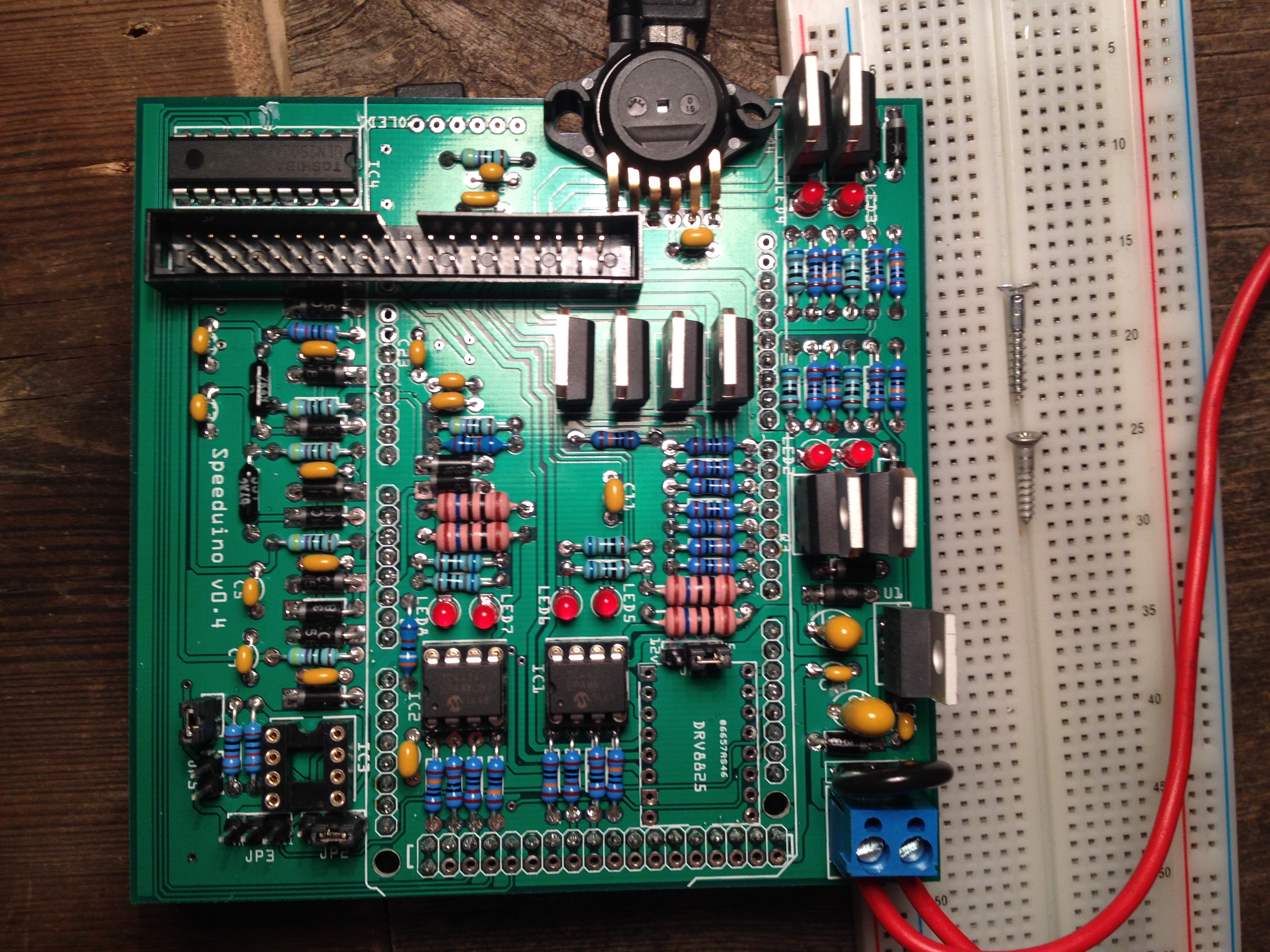
IMG_1083.JPG (2.62 MiB) Viewed 5595 times
By NickZ
#5247
IMG_1083.JPG
IMG_1083.JPG (1.35 MiB) Viewed 5579 times
the square pad is negative closest to the edge of the board.
the diode should have protected it from damage hopefully.
By GMC270
#5257
Aren't the square pads always the positive ones?
I think it should be written down somewhere (like on the board) how to connect the 12V on the terminal.
I could nowhere find how to connect it...

but thanks, when I get home Ill try if the speeduino is still alive :)
User avatar
By cx500tc
#5268
Square pads are usually only used to indicate pin "1" on a connector / component.
On the V.04 board, the square is ground, relatively easy to ID since it's connected to the solder layer around the part.
The round pad is (+); can tell because it connects to U2, diode D15 and caps C15/C16.
By edc_atl
#5272
cx500tc wrote:Square pads are usually only used to indicate pin "1" on a connector / component.
On the V.04 board, the square is ground, relatively easy to ID since it's connected to the solder layer around the part.
The round pad is (+); can tell because it connects to U2, diode D15 and caps C15/C16.
That is correct on the square pads but our boards do not have square pads on the power connections. When you attach a round pad to a ground plane, it adds four tie in corners to it. Makes it look square but it's really not the case, looks more like a small bulls eye.
By GMC270
#5274
It may be a good improvement of the board to mark + and - on the 12V terminal to prevent other newbies from making the same fault.
I short circuited the speeduino via the ignition module, both the speeduino and the ignition module survived but maybe other ignition modules would have been destroyed. Thereby there is a risk of fire.
You cannot know how to connect the 12V power supply without studying the electrical scheme.
I guess marking the board with a + and - should not be a big thing (but I can definately be wrong) and could prevent others from a lot of trouble. JMHO.
By noisymime
#5284
This is a complete oversight on my part. There should definitely have been markings on the board indicating polarity, just as there is on the v0.3 board.

Apologies around this, I will ensure that future revisions have this included.
By raven007
#5290
Also in the future when building boards its always a good idea, if possible, to build the power supply section first and test before continuing. A dead in package regulator (rare but its possible) or other component could cause damage thats difficult to isolate if the entire board is populated then tested. :)

nice first of all, i read all that crap months a[…]

I rewired a few grounds and tested the TPS and rel[…]

Thanks, car runs great now !!! Going to drift even[…]

sauver moteur v8

bonsoir je m appel jean marie et j habite en Franc[…]

Still can't find what you're looking for?