Anything not specifically related to the Speeduino hardware. Eg sensors, bluetooth, displays etc
By Aeroduino
#5599
Hello. I was wondering if someone could in an pedagogic way explain this Speeduino wiring schematics? I would like to use them in my project.
My coil pack is an Bosh coil pack with built in ignitor/logic,( VAG part 032905106B/032905106E) could I use this wiring for this coil?
http://www.ebay.co.uk/itm/NEW-AUDI-SEAT ... SwxH1T1pG9
Speeduino wiring ignitor output.jpg
Speeduino wiring ignitor output.jpg (113.25 KiB) Viewed 6654 times
Speeduino Power supply.png
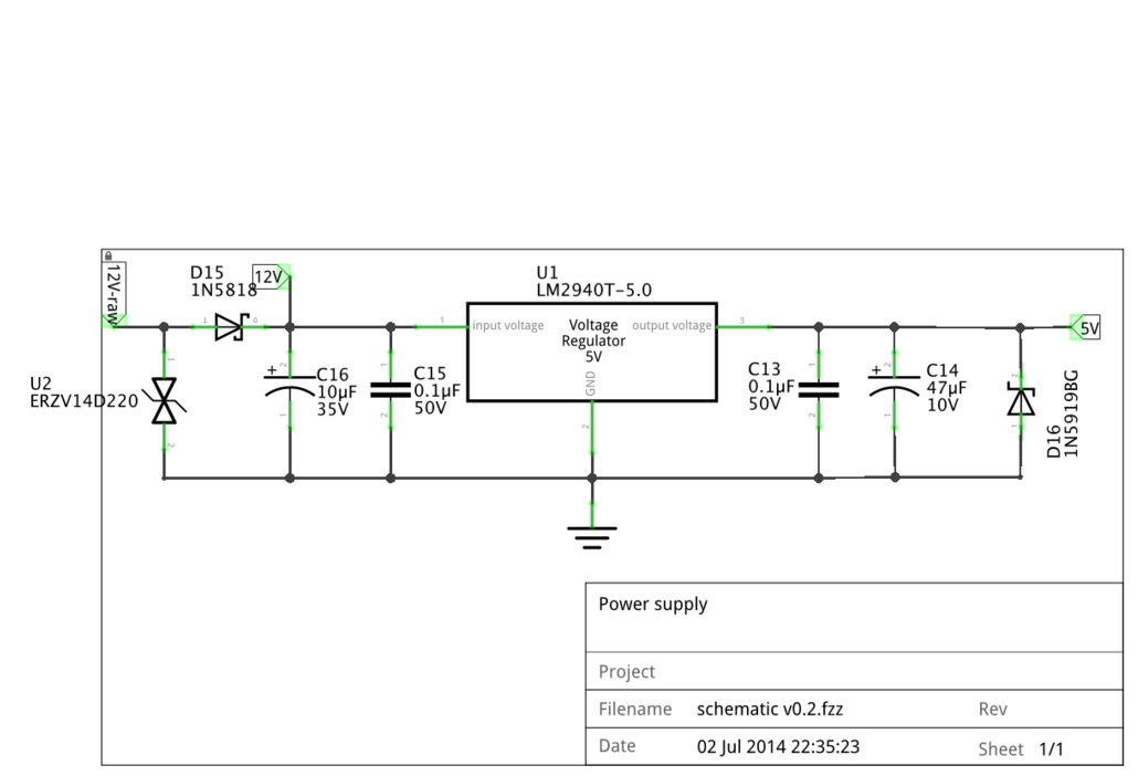
Speeduino Power supply.png (68.39 KiB) Viewed 6654 times
Speeduino Battery reference.png
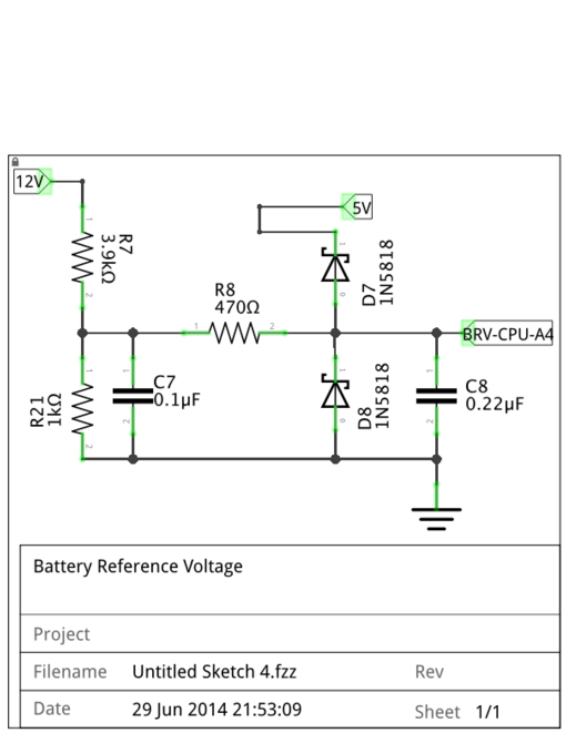
Speeduino Battery reference.png (50.54 KiB) Viewed 6654 times
By berthfield
#5601
If my assumptions are correct those are not actually a wiring diagram but are actually showing the schematic of the board itself. The actual connections to be made between your car and the speeduino board depend on the version of the board you are using.

There is a start at detailing the connections needed at http://speeduino.com/wiki/index.php/Wiring. I can give you a more detailed response if you let me know the actual board you are using.
By noisymime
#5615
Aeroduino wrote:Hello. I was wondering if someone could in an pedagogic way explain this Speeduino wiring schematics? I would like to use them in my project.
My coil pack is an Bosh coil pack with built in ignitor/logic,( VAG part 032905106B/032905106E) could I use this wiring for this coil?
http://www.ebay.co.uk/itm/NEW-AUDI-SEAT ... SwxH1T1pG9
Speeduino wiring ignitor output.jpg
Speeduino Power supply.png
Speeduino Battery reference.png
If I'm understanding you correctly, you want to use the circuit designs from Speeduino in your own project, without actually using a Speeduino board, is that right? If that is the case, then yes, these circuits will definitely work well for you. They are well tested and designed to be portable for use in different projects (Just as you're doing).
By Aeroduino
#5620
Yes I would like to use this circuits for my Arduino UNO ignition system. I would like to use it for connecting the uno to the VAG coil pack and to power the UNO from the car battery.
I am not quit sure what the Battery reference diagram is for? Is it for measuring the battery voltage and use it as a fault code or HMI signal?
I would like someone to explain what the circuits do, in plain english text. I know basic electronics, but want to be sure that I understand the circuits right.

Thank you for your help!
By noisymime
#5621
Aeroduino wrote:I am not quit sure what the Battery reference diagram is for? Is it for measuring the battery voltage and use it as a fault code or HMI signal?
Yes, the battery reference circuit is a voltage divider (with filtering and protection) for measuring the current voltage of the main 12v system.

This is used for things that are voltage dependent such as dwell time. When the voltage drops below 12v, you need to increase your dwell time to compensate.
By Aeroduino
#5624
Ok great! I guess how much the compensation should be depends on the coil pack used. But if someone have a graph or table for the dwell time/voltage on the VAG coil pack 032905106B/032905106E , I Would Be Happy!

So I guess I need to draw a diagram of my current setup for you to help me decide the proper wiring between my UNO and coil pack?
My project and code is more described here:
https://forum.arduino.cc/index.php?topic=369684.0
By Aeroduino
#5988
Ok so I have made an impressive wiring diagram! (Sorry for the amateur type of work). But could you electro engineers take a look at this and tell me whats right and wrong?
The coil pack is supused to have 4 ignition plugs, but I guess you get the idea.
Aeroduino_Ign.png
Aeroduino_Ign.png (84.59 KiB) Viewed 6511 times
By edc_atl
#5990
From what I see you might have a few problems, I say might because aviation requirements are a little different than automotive.

First, the LM2940 is a 1A regulator which has enough output to supply your complete board. The second one is somewhat under-used so I would get rid of it and use a single power supply circuit. Unless a backup or redundancy is required then I would put them both in parallel but still keep a single +5V power output.

Second, I would evaluate your battery circuit with the two 3Ah paralleled units, there is a fuse and diode combo that I don't believe it does anything since it is shorted out on the schematics.

Third, ground your coil at the chassis near the location of the coil. Do not run your coil ground wire back to your electronics.

Last, I would re-evaluate your Hall and tach circuits. You should have a single input for your ignition pulse to the arduino and you can use an output to drive your tachometer.

It was a good effort in detail, think about it and see what the end result is.
By Aeroduino
#5993
Thank you for helping me out. I realy appreciate it.
Yes somethimes a redundant system is good in aircrafts, but not always. more components give more hazzle and more possibilities for faults. Tis EIS will be ignition system nr 2 on this engine. There are two plugs for each cylinder and the primary system is an regular aircraft magneto ignition (old clumsy stuff, but still well prooven and accepted).
I had two power supplies becaus an other person told me that the arduino and coil should have a separate supply to get rid of noise. But he did not know about this speeduino wiring. I beleive that the biggest risk component is the arduino (but I dont know), so I have two running parallell. Is this ok or will them interfere each other? Should I put a diode on each output wire from the arduinos?

Yes I see now that the battery circuit is unneccasary. My thoght was to protect them from eachother if one would get damaged. What will happen if one battery goes bad and start stealing power from the other one? I still would like to have two small batteries for some redundancy. They will only be used for this ignition system, an tachometer and a radio.

Do you have an idea for a simple analog tachometer tu use with the arduino? I would not like to make my code any slower with an extra routine for an rpm signal. Or am i paranoid? Or is there a tachometer with built in logic to put on the one ignintion output pin?

Should I ground everything to the engine case, battery, arduino, other circuits and coil pack?? The coil pack has a ground pin (dont know if it is common ground or just logic ground) and the coil pack is to be grounded with the mounting bolts to the engine case.

The hall sensor: I am using an bipolar hall latch sensor. The flyweel have 2 magnets, one south and one north pointing out. One digital pin has an interrupt routine for falling edge, and the other pin has an interrupt routine for raising edge. So thats why I need to use two inputs. Thats how I know the crank position.
Aeroduino Ign wring16-02-13.png
Aeroduino Ign wring16-02-13.png (82.38 KiB) Viewed 6495 times
By Aeroduino
#6003
To explain more about the sensor trigger code, please take a look at my code, (I am happy if you find any faults or bad codes :) ):
Code: Select all
/****Simple reliable Electronic Ignition System for 4-stroke 4-cylinder wasted spark ignition system.
*****By Anders Stenhammar. 2016, Sweden **********/

// To be able to manipulate the AVR processor timers:
#include <Avr/interrupt.h>
#include <Avr/io.h>

//Pin definitions:
const byte HallPin1 = 2; // Pin nr 2  to Hall sensor
const byte HallPin2 = 3; // Pin nr 3 is also to Hall sensor
const byte IgnOnPin = 4; // Ignition switch
const byte Ign1Pin = 8;  // (PORTB,0)
const byte Ign2Pin = 12; // (PORTB,4)

volatile unsigned int cranktime;         // Time from 3 degrees to where the coil should start to load.
volatile unsigned int crankingDwellTime; // The time the coil should charge during cranking 
volatile long int microseconds;          // The microsecondcounter value.
volatile long int half_revolution_time;  // The time it takes for the crank to turn 1/2 revolution.
volatile int runningDwellTime;           // The time the coil should charge during running 
volatile int dwellTime;                  // The time the coil should charge.
volatile int IgnSystem;                  // Statusword for active ign system.
volatile byte IgnOn;


/***********************************************************************/
void setup() {
 
  pinMode(Ign1Pin, OUTPUT);    // Initialize   the Ignition 1 pin as an output.
  pinMode(Ign2Pin, OUTPUT);    // -"-
  pinMode(HallPin1, INPUT_PULLUP); // To get rid of RFI interference
  pinMode(HallPin2, INPUT_PULLUP); // -"-
  pinMode(IgnOnPin, INPUT_PULLUP); // -"-
  
  bitClear(PORTB, 0);          //digitalWrite(Ign2Pin, LOW);  //Turn the ignition off in case it's on
  bitClear(PORTB, 4);          //digitalWrite(Ign1Pin, LOW);  //   -"-

  attachInterrupt(digitalPinToInterrupt(HallPin1), SensorOn, RISING);   //Hall sensor DI for Ignition 1
  attachInterrupt(digitalPinToInterrupt(HallPin2), SensorOff, FALLING); //-"- 2
  
  crankingDwellTime = 4000;     //in uS
  runningDwellTime = 3000;      //in uS
  half_revolution_time = 0;                                  
  IgnSystem = 0;               // No ignition system is active (cranking mode).
  IgnOn=LOW;
  IgnOn = digitalRead(IgnOnPin);
   
  /********** Setup timer2*************/
  noInterrupts();
  TCCR2A = 0;               // Turn off Control register for waveform generation
  TCCR2B = 0;               // Turn off noise cancelling, turn off edge select, waveform gen mode 0, 
  TCCR2A |= (1 << WGM21);   // Turn on CTC mode (so it will start again) automatically
  TIMSK2 |= (1 << OCIE2A);  // Set interrupt on compare match.
  OCR2A = 8;                // Prescaler of 64 gives 4uS per tick, 4uS * 8 = 32uS (32uS = 1 degree at ~5100rpm).
  TCNT2  = 0;               // Reset timer counter to 0
  microseconds = 0;         // Preset the us counter variable.
  interrupts();
}
//========================================================================
/* The interrupt action for magnet 1: The Timer starts to count up 32 uS at a time.
**********************/
void SensorOff () {

 if (IgnOn == HIGH){
  half_revolution_time = microseconds;      // For engine speed measurement
  TCNT2 = 0;                                // Reset the timer count to 0
  microseconds = 0;                         // reset the uS counter variable
  TCCR2B |= (1 << CS22);                    // Load 64 prescaler, and this starts the timer2!
   
// While cranking (rpm < 300), the coil nr 2 will start to charge at once.
   if ((half_revolution_time>100000)||(half_revolution_time==0)) {     
    IgnSystem = 2; 
    bitSet(PORTB,4);                       //digitalWrite(Ign2Pin, HIGH); // (Turn on coil 2 charging immediately.)
    dwellTime = crankingDwellTime;          //Setting the dwelltime for cranking.
    cranktime = 0;                          //Setting the cranktime to 0 for immediate coil charging.      
  }
// While running (rpm >= 300), coil nr 2 will be used at next ignition.  
  if ((half_revolution_time<=100000)&&(half_revolution_time!=0)){         
    IgnSystem = 1;                         //start using coil nr1 instead.
    dwellTime = runningDwellTime;          //setting the dwelltime for running         
    }          
   }
  }  
/*========================================================================
 The interrupt action for magnet 2: The Timer starts to count up 32uS at a time.
********************************/
void SensorOn () {

  if (IgnOn == HIGH){
   half_revolution_time = microseconds;      // For engine speed measurement
  TCNT2 = 0;                                // Reset the timer count to 0
  microseconds = 0;                         // reset the uS counter variable
   TCCR2B |= (1 << CS22);                    // Load 64 prescaler, and this starts the timer2!
   
// While cranking (rpm < 300), the coil nr 1 will start to charge at once.
 if ((half_revolution_time>100000)||(half_revolution_time==0)) {     
    IgnSystem = 1; 
    bitSet(PORTB,0);                       //digitalWrite(Ign1Pin, HIGH); // (Turn on coil 1 charging immediately,)   
    dwellTime = crankingDwellTime;          //setting the dwelltime for cranking. 
    cranktime = 0;                          //Setting the cranktime to 0 for immediate coil charging.
    }
// While running (rpm >= 300), coil nr 2 will be used at next ignition.       
    if ((half_revolution_time<=100000)&&(half_revolution_time!=0)){        
     IgnSystem = 2;                         //start using coil nr2 instead.
     dwellTime = runningDwellTime;          //setting the dwelltime for running          
     }        
    }
   }  
/*=============================================================================
 The Interrupt Service Routine for Timer2 that will be executed each time the timer reach the compare match register (32uS)*/
 ISR(TIMER2_COMPA_vect) {

  microseconds=microseconds+32;  // Increases the variable "microseconds" by 32 every time the ISR is executed).
   
 /************ coil charging*****************************/
  if ((microseconds >= cranktime) && (microseconds < (cranktime+dwellTime))) {  
   
    if (IgnSystem == 1) {   //If ignitionsystem 1 is selected, then:
      bitSet(PORTB,0);     //(Turn on coil 1 charging.) //digitalWrite(Ign1Pin, HIGH);
    } if (IgnSystem == 2) { //If ignitionsystem 2 is selected, then:
        bitSet(PORTB,4);   //(Turn on coil 2 charging.)  //digitalWrite(Ign2Pin, HIGH);
    }
  }
 /***********Discharge coilspark*******************************************/
  // When the microseconds has reached the cranktime and dwelltime, then:
  if (microseconds >=(cranktime + dwellTime)) {  
    bitClear(PORTB, 0); //digitalWrite(Ign1Pin, LOW);  //( Stop charging coil 1. (Gives spark))
    bitClear(PORTB, 4); // digitalWrite(Ign2Pin, LOW);  // As above. 
            // _________________________________________________________________________________________________________ 
  if (microseconds > 100000) { // If the engine has stopped or still cranking, stop and reset the timer.
    TCCR2B &= ~(1 << CS22);    // Clear the prescaler, and this stops the timer2! 
   TCCR2B = 0;
   microseconds = 0;     
  }
 }
 }
 
/***********************************************************/
void loop() {
  
  IgnOn = digitalRead(IgnOnPin); // Check the status of the ignition switch

 // Ignition advance curve.
//Following numbers are based on a excell sheet with the advance curve attached.

if (half_revolution_time> 6208 ){ ///Advance 0 @ >4100 rpm (rev limitation)
 cranktime=7195-dwellTime;}
 
if ((half_revolution_time<=  7500 ) && (half_revolution_time> 7317 )){ ///Advance 28 @  4000-4100 rpm (rev limitation)
 cranktime=6208-dwellTime;}

 if ((half_revolution_time<=  9091 ) && (half_revolution_time> 7500 )){ ///Advance  28 @  4000-3300 rpm 
 cranktime=7525-dwellTime;}

if ((half_revolution_time<=  10000 ) && (half_revolution_time> 9091 )){ ///Advance 27,5 @  3300-3000 rpm
 cranktime=8306-dwellTime;}

if ((half_revolution_time<=  10714 ) && (half_revolution_time> 10000 )){ ///Advance 27  @  3000-2800 rpm
 cranktime=8929-dwellTime;}

if ((half_revolution_time<= 11111 ) && (half_revolution_time>  10714 )){ ///Advance 26  @  2800-2700 rpm
 cranktime=9321-dwellTime;}

 if ((half_revolution_time<= 12500  ) && (half_revolution_time> 11111 )){ ///Advance 24 @  2700-2400 rpm
 cranktime=10625-dwellTime;}

if ((half_revolution_time<= 15000  ) && (half_revolution_time> 12500 )){ ///Advance 22 @  2400-2000 rpm
 cranktime=12917-dwellTime;}

if ((half_revolution_time<= 15789  ) && (half_revolution_time> 15000 )){ ///Advance 20 @  2000-1900 rpm
 cranktime=13772-dwellTime;}

if ((half_revolution_time<= 16667  ) && (half_revolution_time> 15789 )){ ///Advance 18  1900-1800 rpm
 cranktime=14722-dwellTime;}

if ((half_revolution_time<= 18750 ) && (half_revolution_time>= 16667 )){ //Advance 16 @ 1800-1600 rpm 
cranktime=16771-dwellTime;}

if ((half_revolution_time<= 20000 ) && (half_revolution_time>= 18750 )){ //Advance 14 @ 1600-1500 rpm 
cranktime=18111-dwellTime;}

if ((half_revolution_time<= 21429 ) && (half_revolution_time>=20000  )){ //Advance 12 @ 1500-1400 rpm 
cranktime=19643-dwellTime;}
 
if ((half_revolution_time<=25000  ) && (half_revolution_time>= 21429 )){ //Advance 10 @ 1400-1200 rpm 
cranktime=23194-dwellTime;}

if ((half_revolution_time<=27273  ) && (half_revolution_time>=25000  )){ //Advance 9 @ 1200-1100 rpm 
cranktime=25455-dwellTime;}
 
if ((half_revolution_time<= 30000) && (half_revolution_time>=27273  )){ //Advance 8 @ 1100-1000 rpm 
cranktime=28167-dwellTime;}
 
if ((half_revolution_time<=  33333) && (half_revolution_time>= 30000 )){ //Advance 7,5 @ 1000-900 rpm 
cranktime=31389-dwellTime;}

if ((half_revolution_time<=42857  ) && (half_revolution_time>= 33333 )){ //Advance 7 @ 900-700 rpm 
cranktime=40476-dwellTime;}

if ((half_revolution_time<=50000  ) && (half_revolution_time>= 42857)){ //Advance 7 @ 700-600 rpm 
cranktime=47222-dwellTime;}

if ((half_revolution_time<= 75000 ) && (half_revolution_time>= 50000 )){ //Advance 9 @ 600-400 rpm 
cranktime=70000-dwellTime;}

if ((half_revolution_time<=  85714) && (half_revolution_time>= 75000 )){ //Advance 2 @ 400-350 rpm 
cranktime=83333-dwellTime;}

if ((half_revolution_time<= 100000 ) && (half_revolution_time>= 85714 )){ //Advance -2,5 @ 350-300 rpm 
cranktime=99722-dwellTime;}

}
// Thank you for helping me improve this code. Please send feedback to anders.stenhammar84@gmail.com 


nice first of all, i read all that crap months a[…]

I rewired a few grounds and tested the TPS and rel[…]

Thanks, car runs great now !!! Going to drift even[…]

sauver moteur v8

bonsoir je m appel jean marie et j habite en Franc[…]

Still can't find what you're looking for?