For any add-on boards such as VR conditioners, optos and OEM interface boards
By Old Grey
#11217
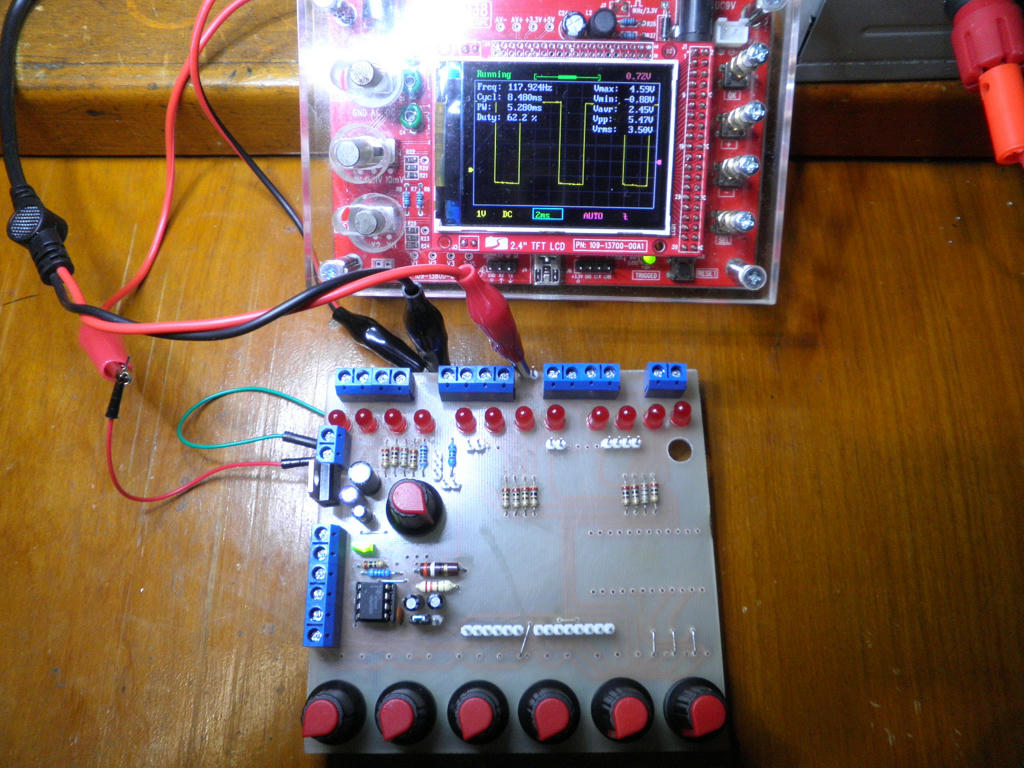
I have 4 different circuits, all with different components, separately working, and they all have a neg component. I tried with PS, PS with reg + & - caps, and even battery power. Unless it's the scope, the only commonalty, I don't know what's up with the wave. They're all basically the same as the pic at the top of the page, but with different values.

I inverted the trans with 5V to "C" and res on "E" to GND, and tapped the wave off the "E" and it fixed the invert. Unfortunately coming off the trans it always produces a smaller Vmax compared to pin 3 on the 555. I'll have more of a play when I get in the mood.

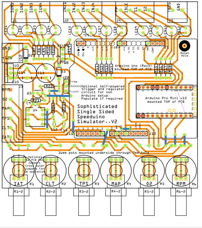
This is pretty close to final, but using edc's osc circuit mod-ed by me. If I can get a simpler more reliable osc circuit I will swap it out.
Image
You will have to "save" it to zoom in.

EDIT - new pic
Last edited by Old Grey on Fri Aug 05, 2016 10:00 am, edited 1 time in total.
By androidcho
#11219
Old Grey wrote:I inverted the trans with 5V to "C" and res on "E" to GND, and tapped the wave off the "E" and it fixed the invert. Unfortunately coming off the trans it always produces a smaller Vmax compared to pin 3 on the 555. I'll have more of a play when I get in the mood.
.
I think that you'll need to place a base resistor with smaller value. 680Ohm to 1K maybe.. You can even try with pot attached insead of the resistor.
By Yury
#42982
Hello everyone !!! I simplified the scheme of Old Gray a little by removing the 555 generator and building it on an arduino-nano. Version with a potentiometer on RPM. If there are people who want to repeat my scheme, write how it works, I have no way to check, I did not assemble speeduino. Thank you Sorry for my English !!! Google translator helps !!!
https://easyeda.com/warlockwolf47/simulator
Attachments
IMG_20190701_184144.png
IMG_20190701_184144.png (933.12 KiB) Viewed 5424 times
11.png
11.png (408.01 KiB) Viewed 5424 times
By subzero
#46994
Yury wrote: Wed May 20, 2020 2:10 pm Hello everyone !!! I simplified the scheme of Old Gray a little by removing the 555 generator and building it on an arduino-nano. Version with a potentiometer on RPM. If there are people who want to repeat my scheme, write how it works, I have no way to check, I did not assemble speeduino. Thank you Sorry for my English !!! Google translator helps !!!
https://easyeda.com/warlockwolf47/simulator
your dsign lacks a ground@ rpm pot
  • 1
  • 10
  • 11
  • 12
  • 13
  • 14

@PSIG Thank you Dave 👍 I will do some 'probing'. […]

Thank you. Ill try as soon as I can. These setti[…]

BMW E23 M30B28

cps.PNG With the crank at TDC, rotation is clo[…]

Ok, here is the first version of the adapter plate[…]

Still can't find what you're looking for?